OUR PRODUCTS ABOUT CONTREC MEET OUR TEAM NEWS CONTACT

Controllers by Series

100 Series 200 Series 400 Series 515 Series Trac-50 LoadPro® Accessories

Products by Functionality

Accessories

Batch Controllers

- Batch/Additive Controllers

- Batch/Flow Controllers

- Batch/Ratio Controllers

- Standard Batch Controllers

Density Computers

Flow Computers

- General Flow Computers

- General Gas Flow Computers

- Heat Calculators

- Mass Flow Computers

- Master Proving Flow Computers

- Natural Gas Flow Computers

- Open Channel Flow Computers

- Special Application Flow Computers

- Steam Flow Computers

Flow Rate Totalisers

- Hazardous Area Flow Rate Totalisers

- Safe Area Flow Rate Totalisers

Level IndicatorsLoad ControllersSite AccessTruck Registers

Products by Industries

AviationBarge & Rail TransportBiofuels ProductionChemical & PharmaceuticalFood & BeverageFuel DepotGas Storage & DistributionMineral MiningNuclearOil & GasOil RefineryPower/EnergyWater & Waste Treatment

Explore Our Products

High quality and accurate, control and flow meters


Use the easy-to-use ‘FILTER BY’ selection boxes to help fine-tune your search.

100 Series

100 Series

Economical, Highly Accurate Instruments for the Process Industry

The 100 Series is a range of economical, yet highly accurate, process instruments for use in field applications where a robust weatherproof IP67 unit will provide the best solution.

All models feature simple programming, large display and input linearisation for increased accuracy.

For more information on Contrec's 100 Series, please complete and submit our enquiry form.

Read More

102A – Flow Rate Totaliser

Typical plant diagram

102A – Flow Rate Totaliser Diagram
102A – Flow Rate Totaliser

102A – Flow Rate Totaliser

102D – Rate Totaliser

Typical plant diagram

102D – Rate Totaliser Diagram
102D – Rate Totaliser

102D – Rate Totaliser

103D – Rate Totaliser – DC Powered

Typical plant diagram

103D – Rate Totaliser – DC Powered Diagram
103D – Rate Totaliser – DC Powered

103D – Rate Totaliser – DC Powered

104D – Rate Totaliser – Loop Powered

Typical plant diagram

104D – Rate Totaliser – Loop Powered Diagram
104D – Rate Totaliser – Loop Powered

104D – Rate Totaliser – Loop Powered

114D – Batch Controller – Frequency/Pulse Input

Typical plant diagram

114D – Batch Controller – Frequency/Pulse Input Diagram
114D – Batch Controller – Frequency/Pulse Input

114D – Batch Controller – Frequency/Pulse Input

120A – Level Monitor

Typical plant diagram

120A – Level Monitor Diagram
120A – Level Monitor

120A – Level Monitor

150A – Process Level Indicator

Typical plant diagram

150A – Process Level Indicator Diagram
150A – Process Level Indicator

150A – Process Level Indicator

200 Series

200 Series

Highly Accurate Field Instrumentation for Hazardous Areas

The 200 Series is a range of intrinsically safe, highly accurate process instruments for use in field applications where a robust, weatherproof IP67 unit will provide the best solution.

All models feature simple programming, large display and input linearisation for increased accuracy.

For more information on Contrec's 200 Series, please complete and submit our enquiry form.

Read More

202A – Analogue Input Rate Totaliser

Typical plant diagram

202A – Analogue Input Rate Totaliser Diagram
202A – Analogue Input Rate Totaliser

202A – Analogue Input Rate Totaliser

202D – Flow Totaliser – Battery, Loop or DC Powered

Typical plant diagram

202D – Flow Totaliser – Battery, Loop or DC Powered Diagram
202D – Flow Totaliser – Battery, Loop or DC Powered

202D – Flow Totaliser – Battery, Loop or DC Powered

212 – Heat Calculator

Typical plant diagram

212 – Heat Calculator Diagram
212 – Heat Calculator

212 – Heat Calculator

214D – Batch Controllers – Pulse/Frequency Input – ATEX/IECEx

Typical plant diagram

214D – Batch Controllers – Pulse/Frequency Input – ATEX/IECEx Diagram
214D – Batch Controllers – Pulse/Frequency Input – ATEX/IECEx

214D – Batch Controllers – Pulse/Frequency Input – ATEX/IECEx

220 – Level Monitor – ATEX

Typical plant diagram

220 – Level Monitor – ATEX Diagram
220 – Level Monitor – ATEX

220 – Level Monitor – ATEX

250 – Process Indicator – Loop Powered

Typical plant diagram

250 – Process Indicator – Loop Powered Diagram
250 – Process Indicator – Loop Powered

250 – Process Indicator – Loop Powered

400 Series

400 Series

Providing Clarity, Accuracy and Reliability to the Process and Petroleum Industries

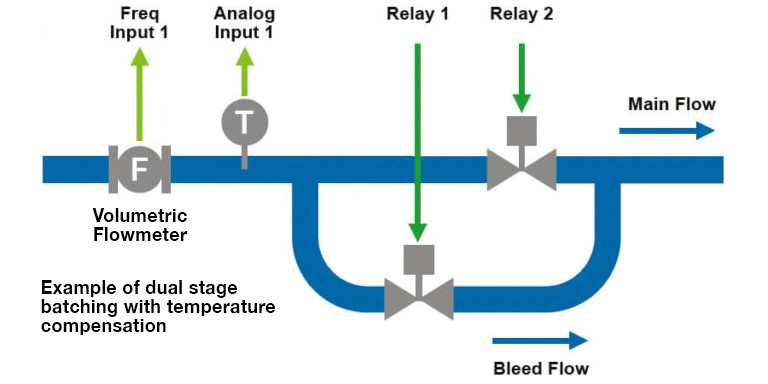
Field proven in thousands of applications worldwide, the Contrec 400 Series instruments provide flexible flow and batch control solutions for a wide range of applications.

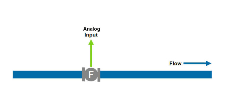
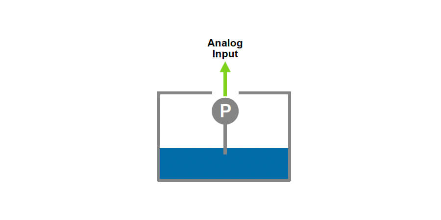
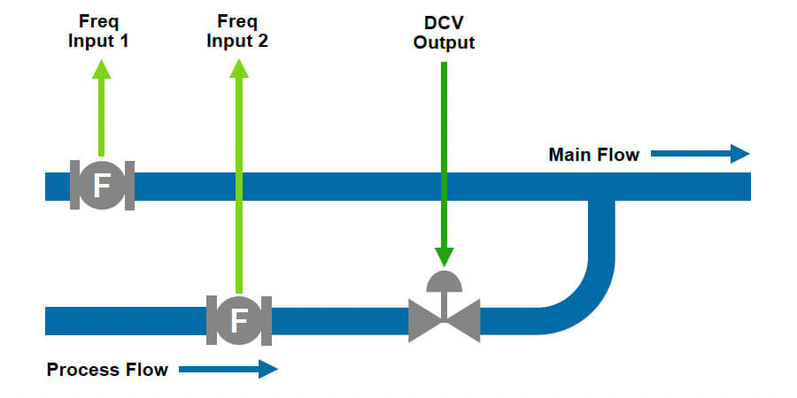
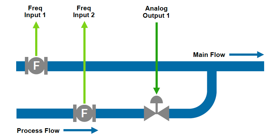
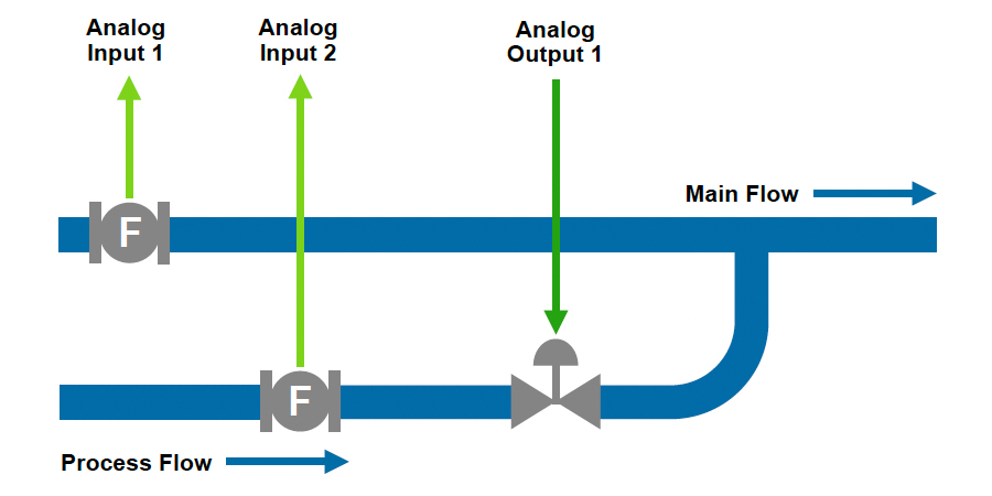
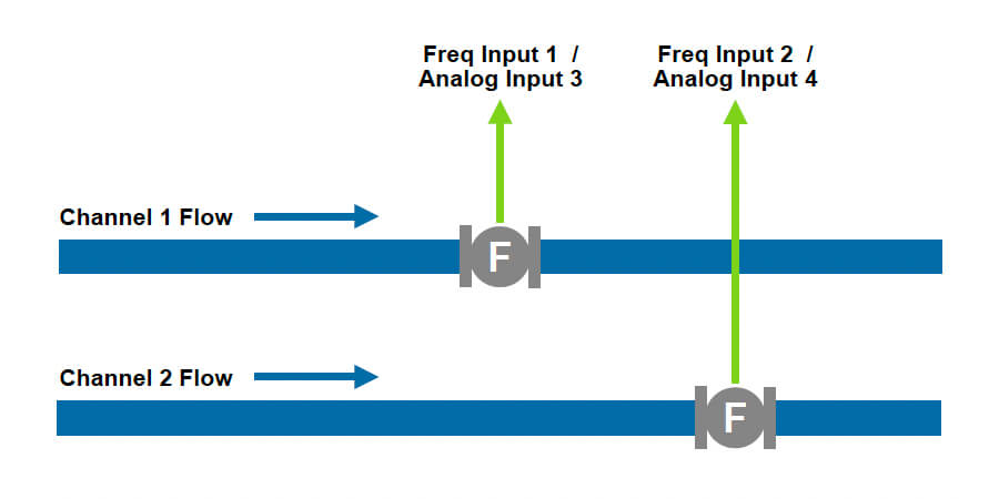
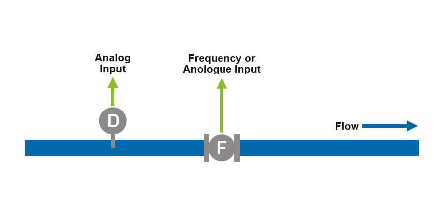
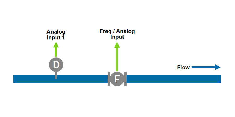
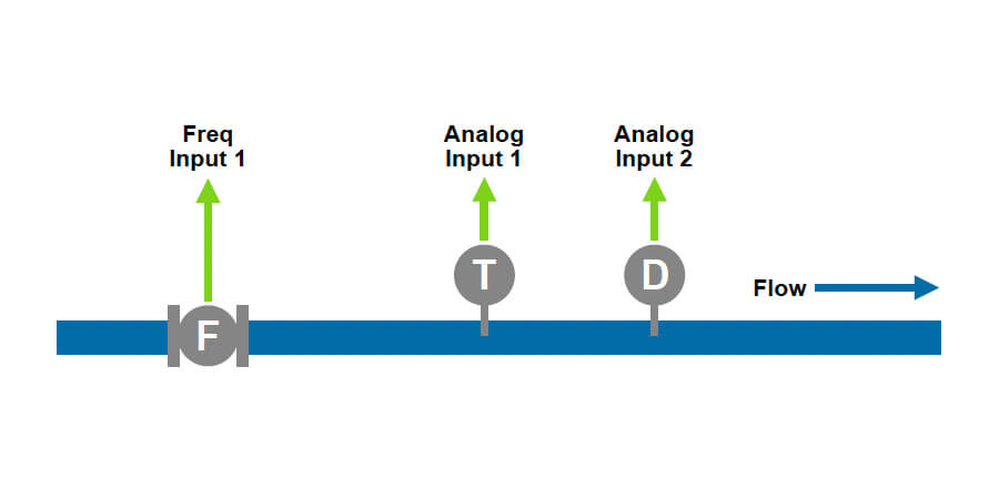
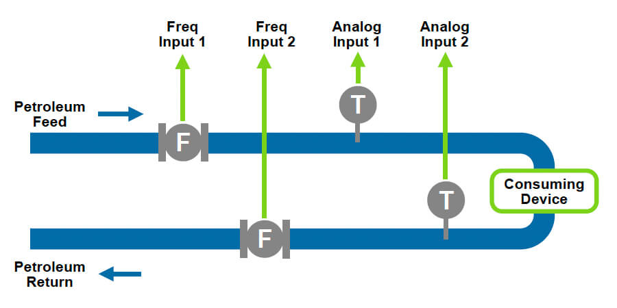
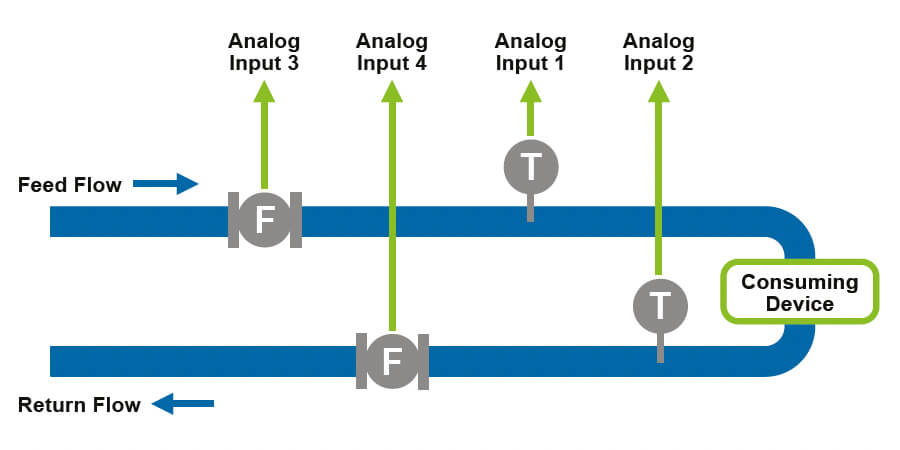
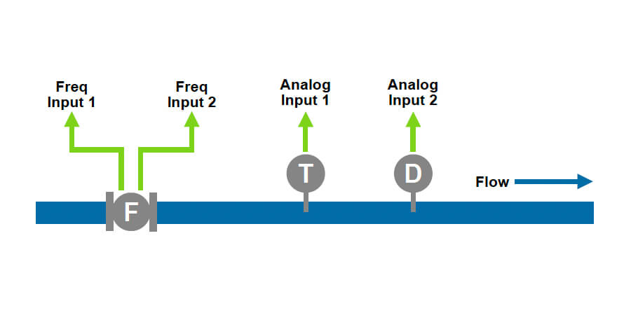
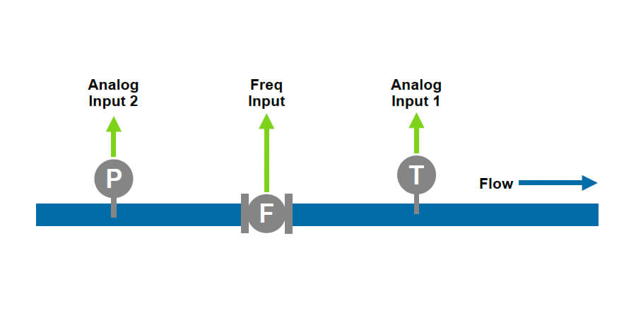
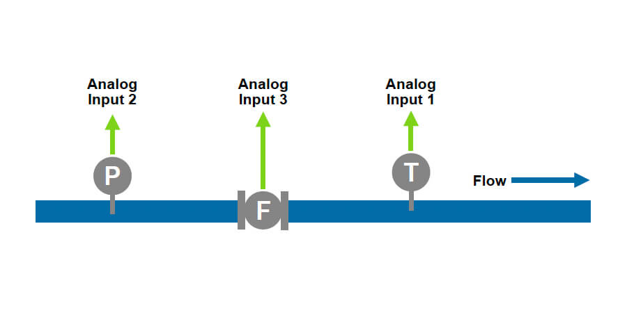
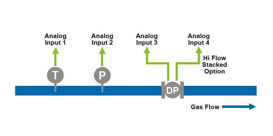
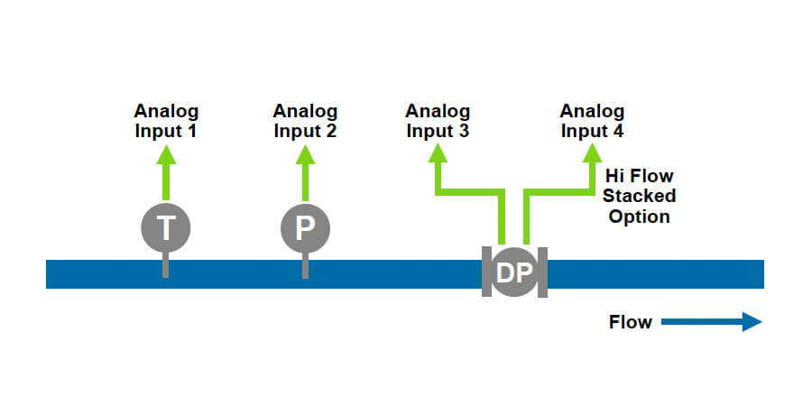
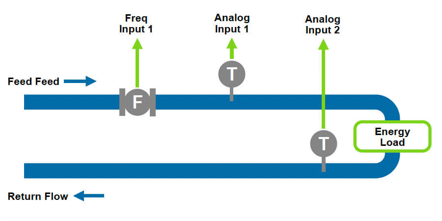
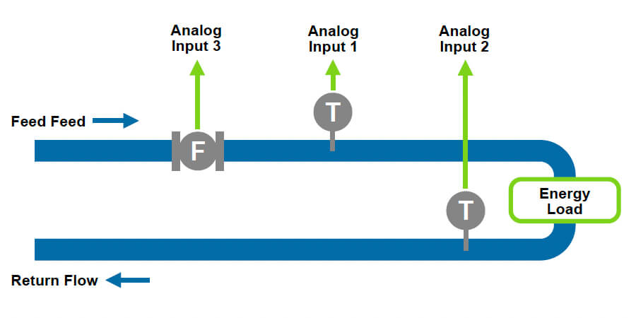
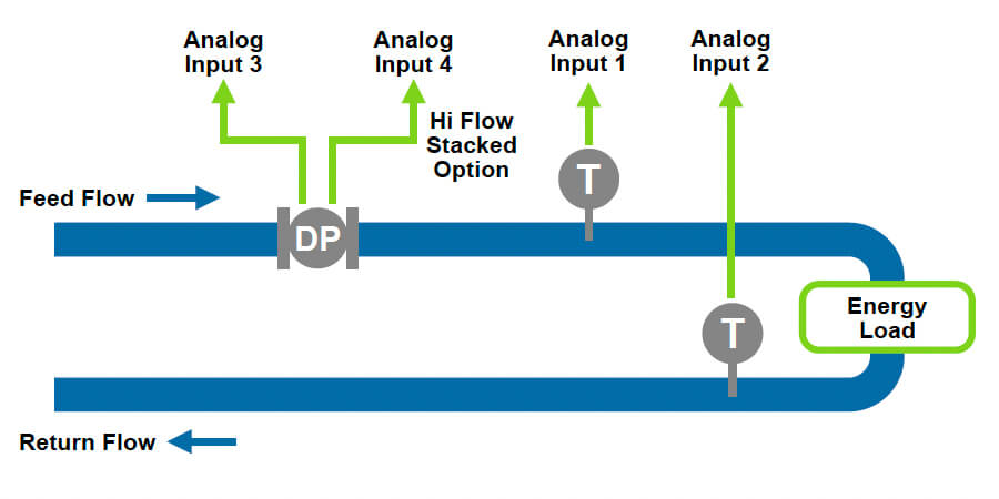
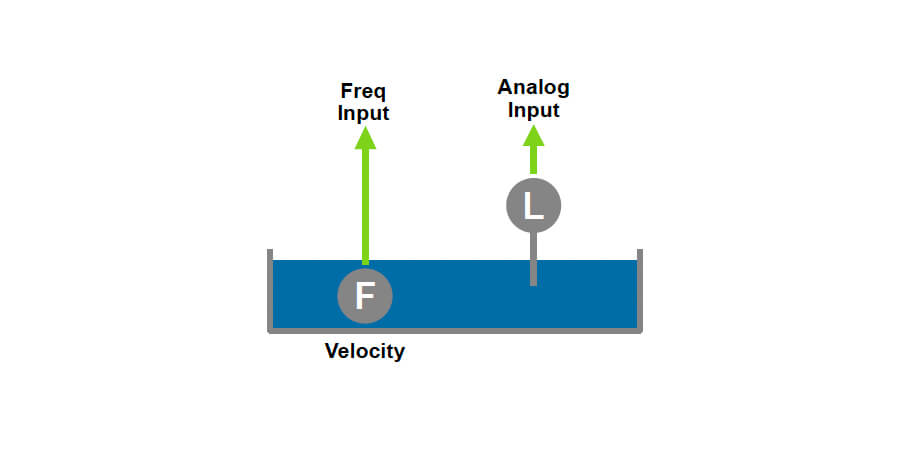
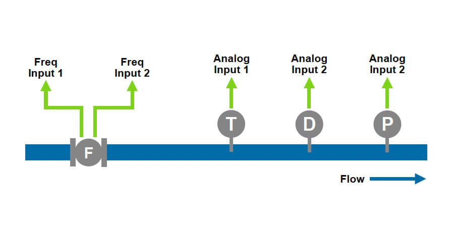
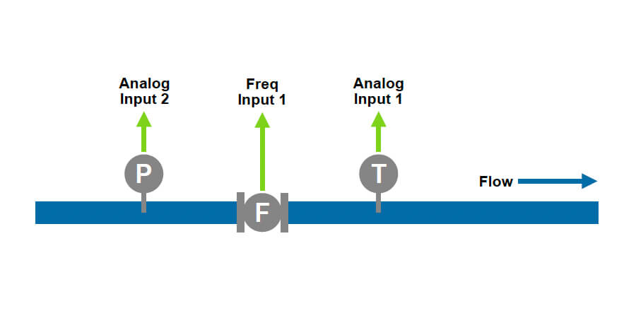
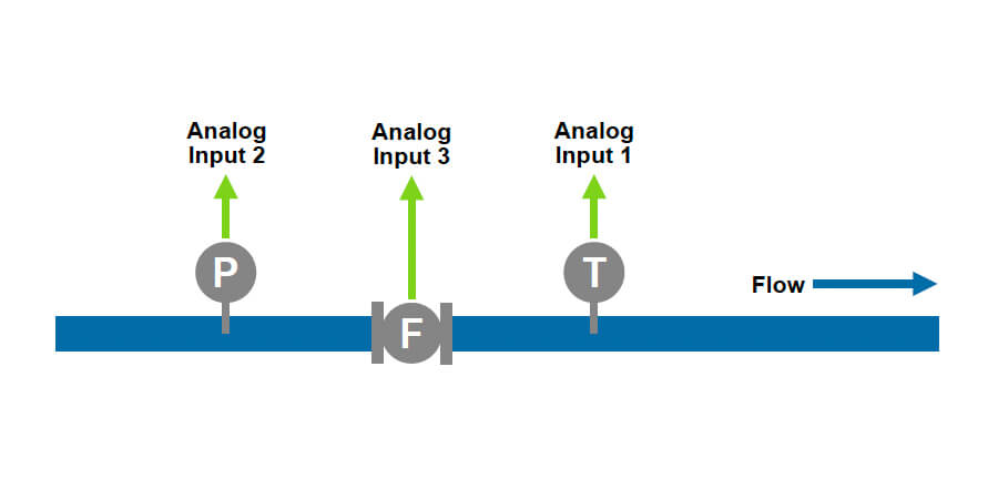
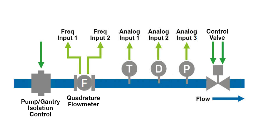
Compatible with virtually every kind of flow meter, the Contrec 400 Series range of Flow Computers and Batch Controllers can accept both frequency or analog type flow signals, including signals from differential pressure devices.

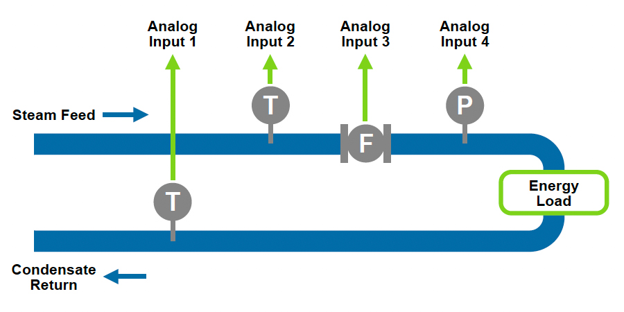
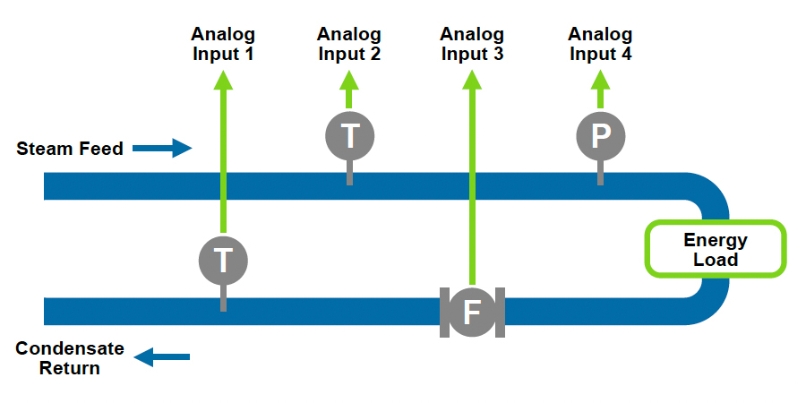
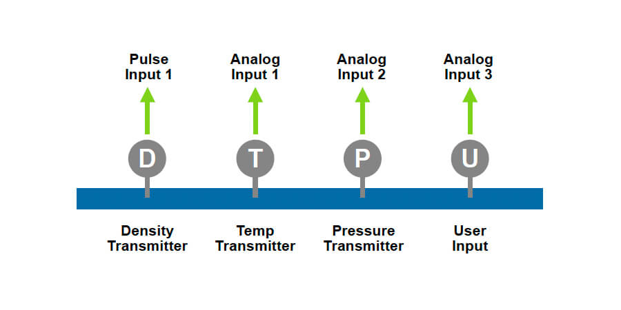
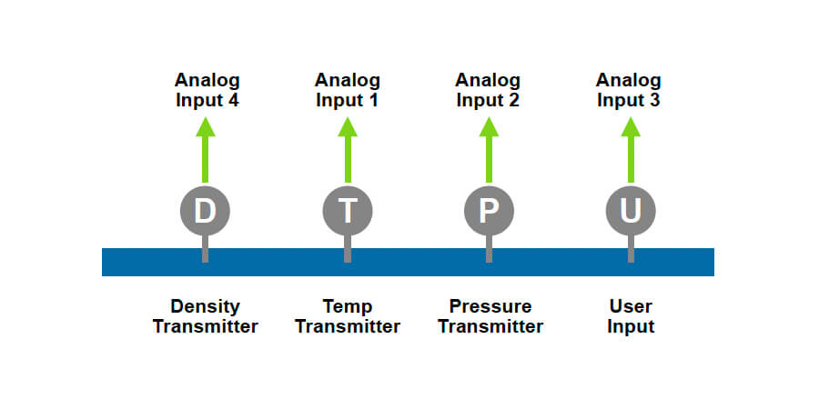
A wide range of output functions and compensation techniques are available to handle most flow applications, including liquid, gas and steam measurement.

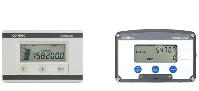
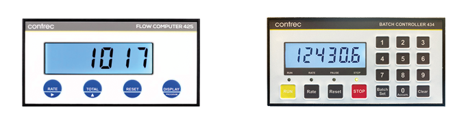
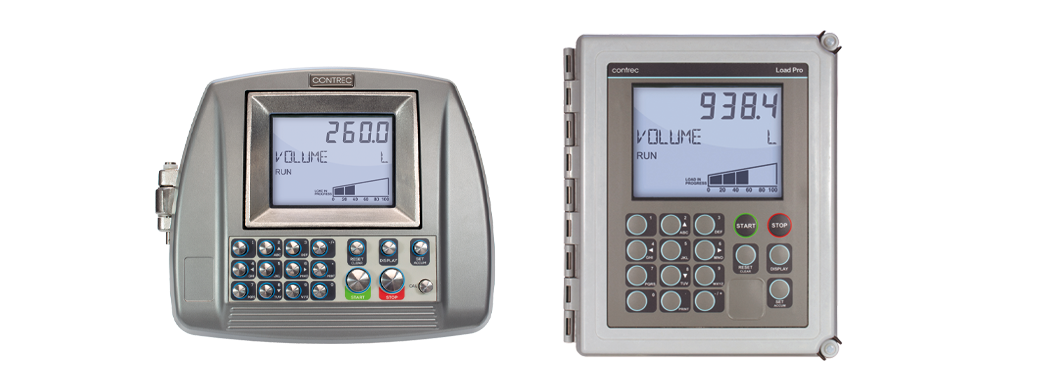
Incorporating the latest surface mount technology and electronic, components, the 424 Batch Controller, 425 Flow Computer and new 434 Batch Controller have evolved to meet the ever changing needs of the process industry. Fully field programmable, the 400 Series has a range of flexibility that enables instruments to be configured on site to meet specific installation requirements.


Maintaining all the best features of the existing 400 series including:

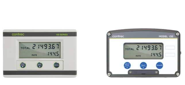
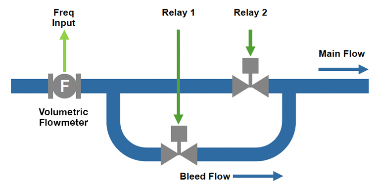
• Large LCD display    • Simple 4 button operation    • Easy to program and operate    • End of batch and pump control output    • Remote start/stop/reset control    • Auto overrun and flow alarm features    • Rugged reliability    • Panel, Field or Explosion-Proof mounting


Now the 424 and 425 models also come with the following features AS STANDARD:

• Adjustable ‘white’ backlight    • Tactile keypad for improved operator interaction    • RS232 & RS485 Communications    • Custom Ticket Printer Header    • Hi & Lo Flow Alarms (425 only)    • Fast response relays for high speed batching    • Software configurable input type    • Universal Mains Power Supply (AC or DC)    • Green, Red and Orange LED status lamps


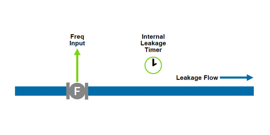
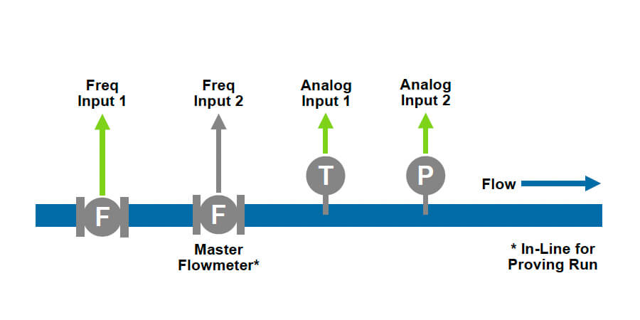
Compatible with virtually any type of pulse or frequency generating flow meters including Turbine, Positive Displacement, Coriolis, Magnetic and Ultrasonic, the Contrec 400 series is fully configurable to display and control in any volumetric or mass engineering units.

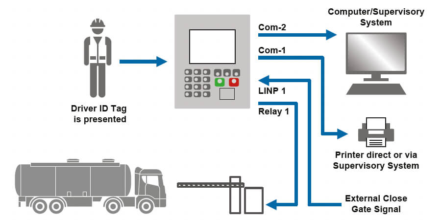
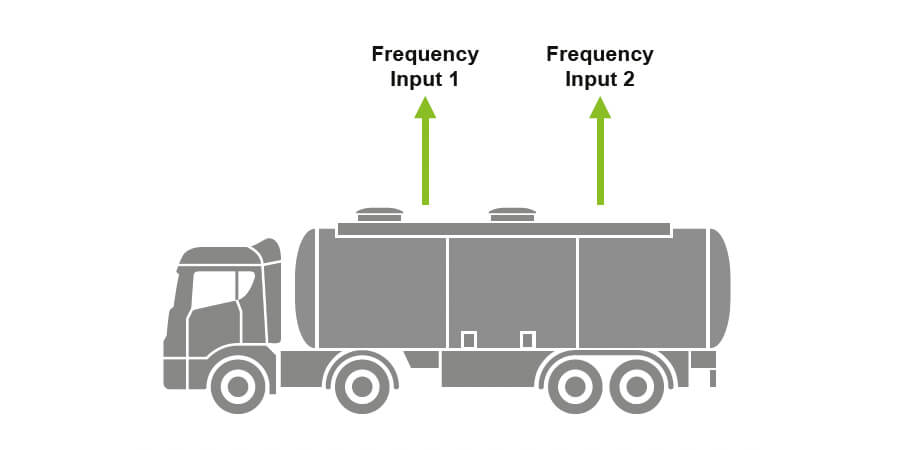
Additionally, having a large LCD backlit displays ensures operators can clearly see what’s happening even in dimly lit installations, whilst the large tactile pushbuttons permit operation using gloved hands, for example in food factories or during tanker loading applications.

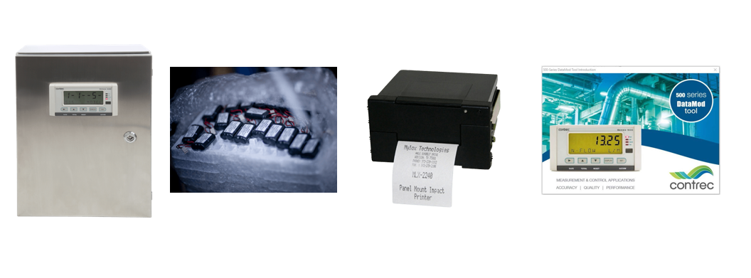
Finally, the instruments come fitted with both RS232 and RS485 communication outputs. These allow the instruments to be monitored and/or controlled remotely from the control room. Additionally they also allow a ticket printer to be connected directly to the device. Many different types of ticket printer are suitable for connection to the 424 and 425. In addition to printing the process data, you can print your custom headers* at the top of each ticket to signify company name, product name, emergency telephone number etc. (*must be factory configured).

With thousands of instruments installed worldwide, Contrec provide accurate and reliable batch and flow solutions you can count on.

For more information on Contrec's 400 Series, please complete and submit our enquiry form.

Read More

424 – Batch Controller

Typical plant diagram

424 – Batch Controller Diagram
424 – Batch Controller

424 – Batch Controller

425 – Flow Computer (General)

Typical plant diagram

425 – Flow Computer (General) Diagram
425 – Flow Computer (General)

425 – Flow Computer (General)

434 – Batch Controller – Frequency Input/Numeric Keyboard

Typical plant diagram

434 – Batch Controller – Frequency Input/Numeric Keyboard Diagram
434 – Batch Controller – Frequency Input/Numeric Keyboard

434 – Batch Controller – Frequency Input/Numeric Keyboard

515 Series

515 Series

Providing Clarity, Accuracy and Reliability to the Process and Petroleum Industries

The 515 Series flow controllers are easy-to-use, easy to understand and offers exceptional flexibility over many applications. This controller is the most advanced model in the 500 Series range. It has more inputs and outputs of higher accuracy, giving it a greater capability and configurability to suit a wide range of applications. There are multiple frequency and analogue inputs which make the controller suitable for applications that require external sensors for temperature, pressure, density, level devices and many other applications.

The 515 series is capable of operating in a wide range of temperature ranges and its plug and play option card makes enhancements easy to undertake without reprogramming. The behavior of the instrument is determined by the function software which is selected from an increasing list of applications in the 500 series program manager.

Critical Environments

Contrec Instruments are flexible and can be mounted in a variety of ways. For safe area or control room environments, the 515 series can be supplied as a panel mount device along with a IP65 front facia.

For installations where the unit would be exposed to the elements, but not in a designated hazardous area, we can supply a variety of field mount enclosures and supply the Contrec unit fitted and pre-wired ready for installation and commissioning. For conditions where there is a risk of explosion or just when the operating conditions require the ultimate in rugged protection, we can supply the controller in our Zone 1 ATEX/CSA (IECEx pending) enclosure. This housing provides a large viewing area and full operation of all the instrument’s features are large, heavy duty, stainless steel push buttons.

For more information on Contrec’s 515 series call us on +44 1422 829944 or email [email protected]
Download our 515 Series brochure

For more information on Contrec's 515 Series, please complete and submit our enquiry form.

Read More

Computer | Controller Categories

Add / Subtract
Condensate & Steam
Consumption
Energy Calculators
Frequency & Mass Flow
Gas (Density Controller)
Ideal Gas
Load Controllers
Meter Proving
Natural Gas
Net Oil
Oil & Petroleum
Open Channel
Pressurised
Single Channel
Site Access

515-AC01 – Additive Injection Controller

Typical plant diagram

515-AC01 – Additive Injection Controller Diagram
515-AC01 – Additive Injection Controller

515-AC01 – Additive Injection Controller

515-BA01 – Batch Additive Controller

Typical plant diagram

515-BA01 – Batch Additive Controller Diagram
515-BA01 – Batch Additive Controller

515-BA01 – Batch Additive Controller

515-BC01 – Dual Stage Batch Controller

Typical plant diagram

515-BC01 – Dual Stage Batch Controller Diagram
515-BC01 – Dual Stage Batch Controller

515-BC01 – Dual Stage Batch Controller

515-BC03 – Mass Batch Controller

Typical plant diagram

515-BC03 – Mass Batch Controller Diagram
515-BC03 – Mass Batch Controller

515-BC03 – Mass Batch Controller

515-BF01 – Frequency Input Batch Controller

Typical plant diagram

515-BF01 – Frequency Input Batch Controller Diagram
515-BF01 – Frequency Input Batch Controller

515-BF01 – Frequency Input Batch Controller

515-BF02 – Analogue Input Batch Controller

Typical plant diagram

515-BF02 – Analogue Input Batch Controller Diagram
515-BF02 – Analogue Input Batch Controller

515-BF02 – Analogue Input Batch Controller

515-BF03 – Frequency Input Batch Controller

Typical plant diagram

515-BF03 – Frequency Input Batch Controller Diagram
515-BF03 – Frequency Input Batch Controller

515-BF03 – Frequency Input Batch Controller

515-BF04 – Analogue Input Batch Controller

Typical plant diagram

515-BF04 – Analogue Input Batch Controller Diagram
515-BF04 – Analogue Input Batch Controller

515-BF04 – Analogue Input Batch Controller

515-BR01 – Frequency Input Batch/Ratio Controller

Typical plant diagram

515-BR01 – Frequency Input Batch/Ratio Controller Diagram
515-BR01 – Frequency Input Batch/Ratio Controller

515-BR01 – Frequency Input Batch/Ratio Controller

515-BR02 – Analogue Input Batch/Ratio Controller

Typical plant diagram

515-BR02 – Analogue Input Batch/Ratio Controller Diagram
515-BR02 – Analogue Input Batch/Ratio Controller

515-BR02 – Analogue Input Batch/Ratio Controller

515-BR03 – Frequency Input Batch/Ratio Controller

Typical plant diagram

515-BR03 – Frequency Input Batch/Ratio Controller Diagram
515-BR03 – Frequency Input Batch/Ratio Controller

515-BR03 – Frequency Input Batch/Ratio Controller

515-BR04 – Analogue Input Batch/Ratio Controller

Typical plant diagram

515-BR04 – Analogue Input Batch/Ratio Controller Diagram
515-BR04 – Analogue Input Batch/Ratio Controller

515-BR04 – Analogue Input Batch/Ratio Controller

515-BS01 – Secure Access Batch Controller

Typical plant diagram

515-BS01 – Secure Access Batch Controller Diagram
515-BS01 – Secure Access Batch Controller

515-BS01 – Secure Access Batch Controller

515-BS03 – Secure Dual Stage Batch Controller

Typical plant diagram

515-BS03 – Secure Dual Stage Batch Controller Diagram
515-BS03 – Secure Dual Stage Batch Controller

515-BS03 – Secure Dual Stage Batch Controller

515-BT01 – Secure Dual Stage Batch Controller

Typical plant diagram

515-BT01 – Secure Dual Stage Batch Controller Diagram
515-BT01 – Secure Dual Stage Batch Controller

515-BT01 – Secure Dual Stage Batch Controller

515-CB01 – Frequency Input Blending Controller

Typical plant diagram

515-CB01 – Frequency Input Blending Controller Diagram
515-CB01 – Frequency Input Blending Controller

515-CB01 – Frequency Input Blending Controller

515-CB02 – Frequency Input Secure Blending Controller

Typical plant diagram

515-CB02 – Frequency Input Secure Blending Controller Diagram
515-CB02 – Frequency Input Secure Blending Controller

515-CB02 – Frequency Input Secure Blending Controller

515-CR01 – Single Loop Process Controller

Typical plant diagram

515-CR01 – Single Loop Process Controller Diagram
515-CR01 – Single Loop Process Controller

515-CR01 – Single Loop Process Controller

515-CR02 – Analogue Input Batch Ratio Controller

Typical plant diagram

515-CR02 – Analogue Input Batch Ratio Controller Diagram
515-CR02 – Analogue Input Batch Ratio Controller

515-CR02 – Analogue Input Batch Ratio Controller

515-CS02 – Condensate & Steam Flow Computer

Typical plant diagram

515-CS02 – Condensate & Steam Flow Computer Diagram
515-CS02 – Condensate & Steam Flow Computer

515-CS02 – Condensate & Steam Flow Computer

515-CS12 – Condensate & Steam Flow Computer

Typical plant diagram

515-CS12 – Condensate & Steam Flow Computer Diagram
515-CS12 – Condensate & Steam Flow Computer

515-CS12 – Condensate & Steam Flow Computer

515-DG01 – Density Coverter (Gas)

Typical plant diagram

515-DG01 – Density Coverter (Gas) Diagram
515-DG01 – Density Coverter (Gas)

515-DG01 – Density Coverter (Gas)

515-DG02 – Density Converter

Typical plant diagram

515-DG02 – Density Converter Diagram
515-DG02 – Density Converter

515-DG02 – Density Converter

515-DP01 – Density Converter (Liquid)

Typical plant diagram

515-DP01 – Density Converter (Liquid) Diagram
515-DP01 – Density Converter (Liquid)

515-DP01 – Density Converter (Liquid)

515-FA01 – Add/Subtract, 2-Channel Input (Volume)

Typical plant diagram

515-FA01 – Add/Subtract, 2-Channel Input (Volume) Diagram
515-FA01 – Add/Subtract, 2-Channel Input (Volume)

515-FA01 – Add/Subtract, 2-Channel Input (Volume)

515-FA02 – Add/Subtract, 2-Channel Input (Mass)

Typical plant diagram

515-FA02 – Add/Subtract, 2-Channel Input (Mass) Diagram
515-FA02 – Add/Subtract, 2-Channel Input (Mass)

515-FA02 – Add/Subtract, 2-Channel Input (Mass)

515-FA03 – Add/Subtract, 2-Channel Input (Energy)

Typical plant diagram

515-FA03 – Add/Subtract, 2-Channel Input (Energy) Diagram
515-FA03 – Add/Subtract, 2-Channel Input (Energy)

515-FA03 – Add/Subtract, 2-Channel Input (Energy)

515-FC01 – Single Channel

Typical plant diagram

515-FC01 – Single Channel Diagram
515-FC01 – Single Channel

515-FC01 – Single Channel

515-FC03 – Mass Flow

Typical plant diagram

515-FC03 – Mass Flow Diagram
515-FC03 – Mass Flow

515-FC03 – Mass Flow

515-FN01 – Frequency Input Net Oil (Mass)

Typical plant diagram

515-FN01 – Frequency Input Net Oil (Mass) Diagram
515-FN01 – Frequency Input Net Oil (Mass)

515-FN01 – Frequency Input Net Oil (Mass)

515-FP01 – Petroleum Consumption Flow Computer – 2 Channel Frequency Flow

Typical plant diagram

515-FP01 – Petroleum Consumption Flow Computer – 2 Channel Frequency Flow Diagram
515-FP01 – Petroleum Consumption Flow Computer – 2 Channel Frequency Flow

515-FP01 – Petroleum Consumption Flow Computer – 2 Channel Frequency Flow

515-FP02 – Petroleum Consumption Flow Computer – 2 Channel Analogue Flow

Typical plant diagram

515-FP02 – Petroleum Consumption Flow Computer – 2 Channel Analogue Flow Diagram
515-FP02 – Petroleum Consumption Flow Computer – 2 Channel Analogue Flow

515-FP02 – Petroleum Consumption Flow Computer – 2 Channel Analogue Flow

515-FP03 – Petroleum Consumption Flow Computer – Quadrature Input

Typical plant diagram

515-FP03 – Petroleum Consumption Flow Computer – Quadrature Input Diagram
515-FP03 – Petroleum Consumption Flow Computer – Quadrature Input

515-FP03 – Petroleum Consumption Flow Computer – Quadrature Input

515-GC01 – Ideal Gas Computer – Quadrature Input

Typical plant diagram

515-GC01 – Ideal Gas Computer – Quadrature Input Diagram
515-GC01 – Ideal Gas Computer – Quadrature Input

515-GC01 – Ideal Gas Computer – Quadrature Input

515-GC02 – Ideal Gas Computer – Analogue Flow

Typical plant diagram

515-GC02 – Ideal Gas Computer – Analogue Flow Diagram
515-GC02 – Ideal Gas Computer – Analogue Flow

515-GC02 – Ideal Gas Computer – Analogue Flow

515-GC03 – Ideal Gas Computer – DP Meter (Meter Span)

Typical plant diagram

515-GC03 – Ideal Gas Computer – DP Meter (Meter Span) Diagram
515-GC03 – Ideal Gas Computer – DP Meter (Meter Span)

515-GC03 – Ideal Gas Computer – DP Meter (Meter Span)

515-GC04 – Ideal Gas Computer – DP Meter (ISO/Cone)

Typical plant diagram

515-GC04 – Ideal Gas Computer – DP Meter (ISO/Cone) Diagram
515-GC04 – Ideal Gas Computer – DP Meter (ISO/Cone)

515-GC04 – Ideal Gas Computer – DP Meter (ISO/Cone)

515-GC06 – Ideal Gas Computer – DP Meter (Volumetric Span)

Typical plant diagram

515-GC06 – Ideal Gas Computer – DP Meter (Volumetric Span) Diagram
515-GC06 – Ideal Gas Computer – DP Meter (Volumetric Span)

515-GC06 – Ideal Gas Computer – DP Meter (Volumetric Span)

515-GN01 – Frequency Input, Natural Gas

Typical plant diagram

515-GN01 – Frequency Input, Natural Gas Diagram
515-GN01 – Frequency Input, Natural Gas

515-GN01 – Frequency Input, Natural Gas

515-GN02 – Analogue Input, Natural Gas

Typical plant diagram

515-GN02 – Analogue Input, Natural Gas Diagram
515-GN02 – Analogue Input, Natural Gas

515-GN02 – Analogue Input, Natural Gas

515-GN03 – DP Meter (Mass), Natural Gas

Typical plant diagram

515-GN03 – DP Meter (Mass), Natural Gas Diagram
515-GN03 – DP Meter (Mass), Natural Gas

515-GN03 – DP Meter (Mass), Natural Gas

515-GN04 – DP Meter (ISO/Cone), Natural Gas (AGA-8)

Typical plant diagram

515-GN04 – DP Meter (ISO/Cone), Natural Gas (AGA-8) Diagram
515-GN04 – DP Meter (ISO/Cone), Natural Gas (AGA-8)

515-GN04 – DP Meter (ISO/Cone), Natural Gas (AGA-8)

515-GN05 – DP Meter (AGA-8), Natural Gas (AGA-8)

Typical plant diagram

515-GN05 – DP Meter (AGA-8), Natural Gas (AGA-8) Diagram
515-GN05 – DP Meter (AGA-8), Natural Gas (AGA-8)

515-GN05 – DP Meter (AGA-8), Natural Gas (AGA-8)

515-GN06 – DP Meter (Volumetric Span), Natural Gas (AGA-8)

Typical plant diagram

515-GN06 – DP Meter (Volumetric Span), Natural Gas (AGA-8) Diagram
515-GN06 – DP Meter (Volumetric Span), Natural Gas (AGA-8)

515-GN06 – DP Meter (Volumetric Span), Natural Gas (AGA-8)

515-GN11 – (SGERG) Quadrature Input, Natural Gas (AGA-8)

Typical plant diagram

515-GN11 – (SGERG) Quadrature Input, Natural Gas (AGA-8) Diagram
515-GN11 – (SGERG) Quadrature Input, Natural Gas (AGA-8)

515-GN11 – (SGERG) Quadrature Input, Natural Gas (AGA-8)

515-GN12 – (SGERG) Analogue Flow, Natural Gas (AGA-8)

Typical plant diagram

515-GN12 – (SGERG) Analogue Flow, Natural Gas (AGA-8) Diagram
515-GN12 – (SGERG) Analogue Flow, Natural Gas (AGA-8)

515-GN12 – (SGERG) Analogue Flow, Natural Gas (AGA-8)

515-GN13 – (SGERG) DP Meter (Mass Span), Natural Gas (AGA-8)

Typical plant diagram

515-GN13 – (SGERG) DP Meter (Mass Span), Natural Gas (AGA-8) Diagram
515-GN13 – (SGERG) DP Meter (Mass Span), Natural Gas (AGA-8)

515-GN13 – (SGERG) DP Meter (Mass Span), Natural Gas (AGA-8)

515-GN14 – (SGERG) DP Meter (ISO/Cone), Natural Gas (AGA-8)

Typical plant diagram

515-GN14 – (SGERG) DP Meter (ISO/Cone), Natural Gas (AGA-8) Diagram
515-GN14 – (SGERG) DP Meter (ISO/Cone), Natural Gas (AGA-8)

515-GN14 – (SGERG) DP Meter (ISO/Cone), Natural Gas (AGA-8)

515-GN16 – (SGERG) DP Meter (Volume Metric), Natural Gas (AGA-8)

Typical plant diagram

515-GN16 – (SGERG) DP Meter (Volume Metric), Natural Gas (AGA-8) Diagram
515-GN16 – (SGERG) DP Meter (Volume Metric), Natural Gas (AGA-8)

515-GN16 – (SGERG) DP Meter (Volume Metric), Natural Gas (AGA-8)

515-HC01 – Heat Calculator – Frequency Flow (Volume)

Typical plant diagram

515-HC01 – Heat Calculator – Frequency Flow (Volume) Diagram
515-HC01 – Heat Calculator – Frequency Flow (Volume)

515-HC01 – Heat Calculator – Frequency Flow (Volume)

515-HC02 – Heat Calculator – Analogue Flow (Volume)

Typical plant diagram

515-HC02 – Heat Calculator – Analogue Flow (Volume) Diagram
515-HC02 – Heat Calculator – Analogue Flow (Volume)

515-HC02 – Heat Calculator – Analogue Flow (Volume)

515-HC03 – Heat Calculator – DP Meter (Mass Span)

Typical plant diagram

515-HC03 – Heat Calculator – DP Meter (Mass Span) Diagram
515-HC03 – Heat Calculator – DP Meter (Mass Span)

515-HC03 – Heat Calculator – DP Meter (Mass Span)

515-HC04 – Heat Calculator for stacked DP meters (ISO 5167 and V-Cones)

Typical plant diagram

515-HC04 – Heat Calculator for stacked DP meters (ISO 5167 and V-Cones) Diagram
515-HC04 – Heat Calculator for stacked DP meters (ISO 5167 and V-Cones)

515-HC04 – Heat Calculator for stacked DP meters (ISO 5167 and V-Cones)

515-HC06 – Heat Calculator – DP Meter (Volumetric Span)

Typical plant diagram

515-HC06 – Heat Calculator – DP Meter (Volumetric Span) Diagram
515-HC06 – Heat Calculator – DP Meter (Volumetric Span)

515-HC06 – Heat Calculator – DP Meter (Volumetric Span)

515-HC12 – Heat Calculator – Analogue Flow (Mass)

Typical plant diagram

515-HC12 – Heat Calculator – Analogue Flow (Mass) Diagram
515-HC12 – Heat Calculator – Analogue Flow (Mass)

515-HC12 – Heat Calculator – Analogue Flow (Mass)

515-LK01 – Leak Monitor

Typical plant diagram

515-LK01 – Leak Monitor Diagram
515-LK01 – Leak Monitor

515-LK01 – Leak Monitor

515-LM02 – Single Tank Level Monitor

Typical plant diagram

515-LM02 – Single Tank Level Monitor Diagram
515-LM02 – Single Tank Level Monitor

515-LM02 – Single Tank Level Monitor

515-MP01 – Mass Flow with Master Proving

Typical plant diagram

515-MP01 – Mass Flow with Master Proving Diagram
515-MP01 – Mass Flow with Master Proving

515-MP01 – Mass Flow with Master Proving

515-MP02 – Frequency with Master Proving

Typical plant diagram

515-MP02 – Frequency with Master Proving Diagram
515-MP02 – Frequency with Master Proving

515-MP02 – Frequency with Master Proving

515-OC01 – Open Channel Flow Computer for Frequency Flow Meter and Analog Level Sensors

Typical plant diagram

515-OC01 – Open Channel Flow Computer for Frequency Flow Meter and Analog Level Sensors Diagram
515-OC01 – Open Channel Flow Computer for Frequency Flow Meter and Analog Level Sensors

515-OC01 – Open Channel Flow Computer for Frequency Flow Meter and Analog Level Sensors

515-PP01 – Pressurised Petroleum

Typical plant diagram

515-PP01 – Pressurised Petroleum Diagram
515-PP01 – Pressurised Petroleum

515-PP01 – Pressurised Petroleum

515-SA01 – Site Access Controller

Typical plant diagram

515-SA01 – Site Access Controller Diagram
515-SA01 – Site Access Controller

515-SA01 – Site Access Controller

515-SC01 – Steam Flow Computer – Frequncy Input

Typical plant diagram

515-SC01 – Steam Flow Computer – Frequncy Input Diagram
515-SC01 – Steam Flow Computer – Frequncy Input

515-SC01 – Steam Flow Computer – Frequncy Input

515-SC02 – Steam Flow Computer – Analogue Input

Typical plant diagram

515-SC02 – Steam Flow Computer – Analogue Input Diagram
515-SC02 – Steam Flow Computer – Analogue Input

515-SC02 – Steam Flow Computer – Analogue Input

515-SC03 – Steam Computer – Volume, Mass & Energy

Typical plant diagram

515-SC03 – Steam Computer – Volume, Mass & Energy Diagram
515-SC03 – Steam Computer – Volume, Mass & Energy

515-SC03 – Steam Computer – Volume, Mass & Energy

515-SC04 – Steam Computer – DP Meter (ISO/Cone)

Typical plant diagram

515-SC04 – Steam Computer – DP Meter (ISO/Cone) Diagram
515-SC04 – Steam Computer – DP Meter (ISO/Cone)

515-SC04 – Steam Computer – DP Meter (ISO/Cone)

515-SC05 – Steam Computer – DP Meter (AGA-3)

Typical plant diagram

515-SC05 – Steam Computer – DP Meter (AGA-3) Diagram
515-SC05 – Steam Computer – DP Meter (AGA-3)

515-SC05 – Steam Computer – DP Meter (AGA-3)

515-SC06 – Steam Computer – DP Meter (Volumetric)

Typical plant diagram

515-SC06 – Steam Computer – DP Meter (Volumetric) Diagram
515-SC06 – Steam Computer – DP Meter (Volumetric)

515-SC06 – Steam Computer – DP Meter (Volumetric)

515-TA02 – Dual Channel On-Truck Additive Batch Controller

Typical plant diagram

515-TA02 – Dual Channel On-Truck Additive Batch Controller Diagram
515-TA02 – Dual Channel On-Truck Additive Batch Controller

515-TA02 – Dual Channel On-Truck Additive Batch Controller

Trac-50 Series

Trac-50 Series

Simple, Robust and Accurate Delivery of Fuels, Chemicals and Liquid Food Stuffs

Contrec’s Trac–50 is an intelligent off-loading controller for the safe and accurate discharge of chemicals, fuels, ammonia measurement and other liquids from trucks, railcars, barges and portable metering trolleys.  Superseding the popular Trac-40 Truck Register, the new model comes with a host of new features and communication options to make off-loading of these expensive commodities safe, secure, and fully traceable.

For more information on Contrec's Trac-50 Series, please complete and submit our enquiry form.

Read More
LoadPro Series

LoadPro® Series

Preset Load Controllers for the Accurate Loading of Fuels and Chemicals

LoadPro® is a single arm load controller. Forming part of a tanker loading system, LoadPro® is the ideal load controller for smaller fuel depots and chemical plants.

LoadPro provides a safe and accurate solution for loading fuels, chemicals and any fluids into tankers. Easily integrated with Datamod®, Contrec’s own simple to use reporting software or with most commercial TAS systems, the full alpha numeric keyboard has capabilities of Dual Stage, Digital Valve, and Analogue Valve Control for the reliable and accurate delivery of preset quantities of liquid products.

For more information on Contrec's LoadPro® Series, please complete and submit our enquiry form.

Read More
Accessories Series

Enclosures and Accessories

Contrec’s Enclosures and Accessories complement our flow and process control products, enhancing functionality and ease of use across various applications. These include communication modules, sensors, mounting kits, and protective enclosures designed for rugged industrial environments. By integrating Contrec accessories, users can customise and optimise their systems for improved protection and performance.

For more information on Contrec's Accessories, please complete and submit our enquiry form.

Read More

Selected Filter

Accessories

Contrec's Accessories complement our flow and process control products, enhancing functionality and ease of use across various applications. These include communication modules, sensors, mounting kits, and protective enclosures designed for rugged industrial environments. By integrating Contrec accessories, users can customise and optimise their systems for improved protection and performance.

For more information on Contrec's control solutions, please complete and submit our enquiry form.

Batch Controllers

Contrec Batch Controllers are trusted, high-precision instruments designed to automate and manage batch processing across a wide range of industrial applications. Known for their reliability, accuracy, and ease of use, these controllers offer flexible configuration and robust performance, ensuring smooth, repeatable batching every time. Whether you're handling liquids, gases, or solids, Contrec’s solutions support efficient flow control, reducing waste and downtime while maintaining strict process standards.

For more information on Contrec's control solutions, please complete and submit our enquiry form.

Batch/Additive Controllers

Our Batch and Additive Controllers deliver precise, reliable control for batching and blending operations across a wide range of industries. Engineered for accuracy and ease of use, they help streamline complex processes and improve operational efficiency.

For more information on Contrec's control solutions, please complete and submit our enquiry form.

Batch/Flow Controllers

Contrec Batch and Flow Controllers provide precise, reliable control for liquid measurement and dispensing across a wide range of industrial applications. Designed for accuracy and ease of integration, they ensure consistent performance in both simple and complex flow processes.

For more information on Contrec's control solutions, please complete and submit our enquiry form.

Batch/Ratio Controllers

Contrec's Batch/Ratio Controllers deliver precise control of batching and ingredient ratio blending in automated process systems. They are ideal for applications requiring consistent product quality, offering intuitive operation and reliable performance across diverse industries.

For more information on Contrec's control solutions, please complete and submit our enquiry form.

Density Computers

Contrec’s Density Computers deliver precise, real-time measurement of fluid density, temperature, and concentration across a wide range of industrial applications. Built for reliability and accuracy, they help optimise process control and ensure compliance in even the most demanding environments.

For more information on Contrec's control solutions, please complete and submit our enquiry form.

Flow Computers

Contrec’s flow computers are designed to accurately measure, monitor and control the flow of liquids, gases, or steam in industrial processes. Built for reliability and performance, Contrec’s solutions are trusted worldwide across sectors including oil and gas, water treatment, chemical processing, and food and beverage. Whether it’s batching, blending, or real-time flow adjustment, Contrec controllers offer robust, user-friendly functionality and seamless integration with existing systems. Known for their durability and versatility, they help operators ensure process efficiency, product consistency, and compliance with industry standards.

For more information on Contrec's control solutions, please complete and submit our enquiry form.

Flow Rate Totalisers

Our Flow Rate Totalisers are precision instruments designed to monitor and display real-time flow rates while accurately recording totalised flow volumes. Built for reliability and clarity, these units are widely used across industries including oil & gas, chemical processing, water treatment, and food production. Whether you’re dealing with liquids, gases, or steam, Contrec’s totalisers provide clear, dependable data for process control, batching, and compliance. Known for their robust build and user-friendly interfaces, they offer trusted performance even in demanding environments.

For more information on Contrec's control solutions, please complete and submit our enquiry form.

Flow Computers

Contrec’s precision-engineered devices are designed to accurately measure, monitor and control the flow of liquids, gases, or steam in industrial processes. Built for reliability and performance, Contrec’s solutions are trusted worldwide across sectors including oil and gas, water treatment, chemical processing, and food and beverage. Whether it’s batching, blending, or real-time flow adjustment, Contrec controllers offer robust, user-friendly functionality and seamless integration with existing systems. Known for their durability and versatility, they help operators ensure process efficiency, product consistency, and compliance with industry standards.

For more information on Contrec's control solutions, please complete and submit our enquiry form.

General Gas Flow Computers

Our Flow Computers provide accurate and reliable measurement for natural gas and other gas applications, ensuring compliance with industry standards. Designed for both custody transfer and process monitoring, they support various flow measurement methods and advanced communication options.

For more information on Contrec's control solutions, please complete and submit our enquiry form.

Hazardous Area Flow Rate Totalisers

Contrec’s Flow Rate Totalisers are designed to provide accurate flow measurement and totalisation in explosive and high-risk environments. Built to meet strict safety standards, they ensure reliable performance and safe operation in oil, gas, and chemical industries.

For more information on Contrec's control solutions, please complete and submit our enquiry form.

Heat Calculators

Contrec heat calculators accurately measure and calculate thermal energy in heating and cooling systems, using temperature and flow inputs for precise energy management. Ideal for HVAC and industrial applications, they ensure reliable performance and support energy efficiency monitoring.

For more information on Contrec's control solutions, please complete and submit our enquiry form.

Level Indicators

Contrec's Level Indicators deliver precise and reliable measurement of liquid levels in tanks and vessels across various industrial applications. They are designed for easy installation and offer robust performance in challenging environments.

For more information on Contrec's control solutions, please complete and submit our enquiry form.

Load Controllers

Our Load Controllers provide accurate and efficient management of load batching processes, ensuring precise weight control for consistent product quality. They are built for reliability and ease of integration in industrial weighing and batching systems.

For more information on Contrec's control solutions, please complete and submit our enquiry form.

Mass Flow Computers

Contrec’s flow computers are designed to accurately measure, monitor and control the flow of liquids, gases, or steam in industrial processes. Built for reliability and performance, Contrec’s solutions are trusted worldwide across sectors including oil and gas, water treatment, chemical processing, and food and beverage.

For more information on Contrec's control solutions, please complete and submit our enquiry form.

Master Proving Flow Computers

These Master Proving Flow Computers are high-precision instruments designed for accurate flow measurement and control across industrial applications. Trusted globally, they offer reliable data logging and real-time performance for liquids, gases, and steam systems.

For more information on Contrec's control solutions, please complete and submit our enquiry form.

Natural Gas Flow Computers

Contrec's Flow Computers deliver precise measurement and calculation of natural gas flow, ensuring accuracy for custody transfer and regulatory compliance. Built for reliability in demanding environments, they support industry-standard protocols and integrate easily with existing flow systems.

For more information on Contrec's control solutions, please complete and submit our enquiry form.

Open Channel Flow Computers

These Open Channel Flow Computers accurately measure and monitor flow in open channels and flumes, ensuring reliable data for water management and environmental applications. They offer easy integration with various sensors and support real-time flow calculation and reporting.

For more information on Contrec's control solutions, please complete and submit our enquiry form.

Safe Area Flow Rate Totalisers

Contrec's Flow Rate Totalisers offer precise real-time flow rate measurement and totalisation directly at the measurement site. Designed for rugged industrial environments, they provide easy installation and reliable performance for continuous flow monitoring.

For more information on Contrec's control solutions, please complete and submit our enquiry form.

Site Access

Contrec’s Site Access Unit provides secure, controlled access to restricted or hazardous sites. The controller interface manages vehicle or personnel access through PIN, touch key, or RFID cards, and logs access events internally. It can also interface with supervisory systems via Modbus RTU for centralised monitoring and control.

For more information on Contrec's control solutions, please complete and submit our enquiry form.

Special Application Flow Computers

Contrec designs and manufactures Specialist Application Computers for precise process control and measurement across industrial environments. Trusted globally, their systems deliver reliable performance in even the most demanding conditions.

For more information on Contrec's control solutions, please complete and submit our enquiry form.

Standard Batch Controllers

Contrec Standard Batch Controllers are trusted precision instruments designed for accurate and reliable flow measurement and control across a wide range of industrial applications. Built for performance and ease of use, they help streamline batching processes while maintaining strict control over delivery accuracy.

For more information on Contrec's control solutions, please complete and submit our enquiry form.

Steam Flow Computers

Our Steam Flow Computers provide accurate measurement and calculation of steam flow and energy, essential for efficient steam system management. Designed for industrial applications, they support various flow measurement technologies and deliver reliable real-time data for process optimisation.

For more information on Contrec's control solutions, please complete and submit our enquiry form.

Truck Registers

Our Truck Registers provide precise measurement and recording of liquid volumes during truck loading and unloading operations. They ensure accurate transaction documentation and help prevent product loss or discrepancies. Built for durability, these registers are ideal for use in industrial and transportation environments.

For more information on Contrec's control solutions, please complete and submit our enquiry form.

Your selection:

102A – Flow Rate Totaliser

Typical plant diagram

102A – Flow Rate Totaliser Diagram
102A – Flow Rate Totaliser

102A – Flow Rate Totaliser

102D – Rate Totaliser

Typical plant diagram

102D – Rate Totaliser Diagram
102D – Rate Totaliser

102D – Rate Totaliser

103D – Rate Totaliser – DC Powered

Typical plant diagram

103D – Rate Totaliser – DC Powered Diagram
103D – Rate Totaliser – DC Powered

103D – Rate Totaliser – DC Powered

104D – Rate Totaliser – Loop Powered

Typical plant diagram

104D – Rate Totaliser – Loop Powered Diagram
104D – Rate Totaliser – Loop Powered

104D – Rate Totaliser – Loop Powered

114D – Batch Controller – Frequency/Pulse Input

Typical plant diagram

114D – Batch Controller – Frequency/Pulse Input Diagram
114D – Batch Controller – Frequency/Pulse Input

114D – Batch Controller – Frequency/Pulse Input

120A – Level Monitor

Typical plant diagram

120A – Level Monitor Diagram
120A – Level Monitor

120A – Level Monitor

150A – Process Level Indicator

Typical plant diagram

150A – Process Level Indicator Diagram
150A – Process Level Indicator

150A – Process Level Indicator

202A – Analogue Input Rate Totaliser

Typical plant diagram

202A – Analogue Input Rate Totaliser Diagram
202A – Analogue Input Rate Totaliser

202A – Analogue Input Rate Totaliser

202D – Flow Totaliser – Battery, Loop or DC Powered

Typical plant diagram

202D – Flow Totaliser – Battery, Loop or DC Powered Diagram
202D – Flow Totaliser – Battery, Loop or DC Powered

202D – Flow Totaliser – Battery, Loop or DC Powered

212 – Heat Calculator

Typical plant diagram

212 – Heat Calculator Diagram
212 – Heat Calculator

212 – Heat Calculator

214D – Batch Controllers – Pulse/Frequency Input – ATEX/IECEx

Typical plant diagram

214D – Batch Controllers – Pulse/Frequency Input – ATEX/IECEx Diagram
214D – Batch Controllers – Pulse/Frequency Input – ATEX/IECEx

214D – Batch Controllers – Pulse/Frequency Input – ATEX/IECEx

220 – Level Monitor – ATEX

Typical plant diagram

220 – Level Monitor – ATEX Diagram
220 – Level Monitor – ATEX

220 – Level Monitor – ATEX

250 – Process Indicator – Loop Powered

Typical plant diagram

250 – Process Indicator – Loop Powered Diagram
250 – Process Indicator – Loop Powered

250 – Process Indicator – Loop Powered

424 – Batch Controller

Typical plant diagram

424 – Batch Controller Diagram
424 – Batch Controller

424 – Batch Controller

425 – Flow Computer (General)

Typical plant diagram

425 – Flow Computer (General) Diagram
425 – Flow Computer (General)

425 – Flow Computer (General)

434 – Batch Controller – Frequency Input/Numeric Keyboard

Typical plant diagram

434 – Batch Controller – Frequency Input/Numeric Keyboard Diagram
434 – Batch Controller – Frequency Input/Numeric Keyboard

434 – Batch Controller – Frequency Input/Numeric Keyboard

515-AC01 – Additive Injection Controller

Typical plant diagram

515-AC01 – Additive Injection Controller Diagram
515-AC01 – Additive Injection Controller

515-AC01 – Additive Injection Controller

515-BA01 – Batch Additive Controller

Typical plant diagram

515-BA01 – Batch Additive Controller Diagram
515-BA01 – Batch Additive Controller

515-BA01 – Batch Additive Controller

515-BC01 – Dual Stage Batch Controller

Typical plant diagram

515-BC01 – Dual Stage Batch Controller Diagram
515-BC01 – Dual Stage Batch Controller

515-BC01 – Dual Stage Batch Controller

515-BC03 – Mass Batch Controller

Typical plant diagram

515-BC03 – Mass Batch Controller Diagram
515-BC03 – Mass Batch Controller

515-BC03 – Mass Batch Controller

515-BF01 – Frequency Input Batch Controller

Typical plant diagram

515-BF01 – Frequency Input Batch Controller Diagram
515-BF01 – Frequency Input Batch Controller

515-BF01 – Frequency Input Batch Controller

515-BF02 – Analogue Input Batch Controller

Typical plant diagram

515-BF02 – Analogue Input Batch Controller Diagram
515-BF02 – Analogue Input Batch Controller

515-BF02 – Analogue Input Batch Controller

515-BF03 – Frequency Input Batch Controller

Typical plant diagram

515-BF03 – Frequency Input Batch Controller Diagram
515-BF03 – Frequency Input Batch Controller

515-BF03 – Frequency Input Batch Controller

515-BF04 – Analogue Input Batch Controller

Typical plant diagram

515-BF04 – Analogue Input Batch Controller Diagram
515-BF04 – Analogue Input Batch Controller

515-BF04 – Analogue Input Batch Controller

515-BR01 – Frequency Input Batch/Ratio Controller

Typical plant diagram

515-BR01 – Frequency Input Batch/Ratio Controller Diagram
515-BR01 – Frequency Input Batch/Ratio Controller

515-BR01 – Frequency Input Batch/Ratio Controller

515-BR02 – Analogue Input Batch/Ratio Controller

Typical plant diagram

515-BR02 – Analogue Input Batch/Ratio Controller Diagram
515-BR02 – Analogue Input Batch/Ratio Controller

515-BR02 – Analogue Input Batch/Ratio Controller

515-BR03 – Frequency Input Batch/Ratio Controller

Typical plant diagram

515-BR03 – Frequency Input Batch/Ratio Controller Diagram
515-BR03 – Frequency Input Batch/Ratio Controller

515-BR03 – Frequency Input Batch/Ratio Controller

515-BR04 – Analogue Input Batch/Ratio Controller

Typical plant diagram

515-BR04 – Analogue Input Batch/Ratio Controller Diagram
515-BR04 – Analogue Input Batch/Ratio Controller

515-BR04 – Analogue Input Batch/Ratio Controller

515-BS01 – Secure Access Batch Controller

Typical plant diagram

515-BS01 – Secure Access Batch Controller Diagram
515-BS01 – Secure Access Batch Controller

515-BS01 – Secure Access Batch Controller

515-BS03 – Secure Dual Stage Batch Controller

Typical plant diagram

515-BS03 – Secure Dual Stage Batch Controller Diagram
515-BS03 – Secure Dual Stage Batch Controller

515-BS03 – Secure Dual Stage Batch Controller

515-BT01 – Secure Dual Stage Batch Controller

Typical plant diagram

515-BT01 – Secure Dual Stage Batch Controller Diagram
515-BT01 – Secure Dual Stage Batch Controller

515-BT01 – Secure Dual Stage Batch Controller

515-CB01 – Frequency Input Blending Controller

Typical plant diagram

515-CB01 – Frequency Input Blending Controller Diagram
515-CB01 – Frequency Input Blending Controller

515-CB01 – Frequency Input Blending Controller

515-CB02 – Frequency Input Secure Blending Controller

Typical plant diagram

515-CB02 – Frequency Input Secure Blending Controller Diagram
515-CB02 – Frequency Input Secure Blending Controller

515-CB02 – Frequency Input Secure Blending Controller

515-CR01 – Single Loop Process Controller

Typical plant diagram

515-CR01 – Single Loop Process Controller Diagram
515-CR01 – Single Loop Process Controller

515-CR01 – Single Loop Process Controller

515-CR02 – Analogue Input Batch Ratio Controller

Typical plant diagram

515-CR02 – Analogue Input Batch Ratio Controller Diagram
515-CR02 – Analogue Input Batch Ratio Controller

515-CR02 – Analogue Input Batch Ratio Controller

515-CS02 – Condensate & Steam Flow Computer

Typical plant diagram

515-CS02 – Condensate & Steam Flow Computer Diagram
515-CS02 – Condensate & Steam Flow Computer

515-CS02 – Condensate & Steam Flow Computer

515-CS12 – Condensate & Steam Flow Computer

Typical plant diagram

515-CS12 – Condensate & Steam Flow Computer Diagram
515-CS12 – Condensate & Steam Flow Computer

515-CS12 – Condensate & Steam Flow Computer

515-DG01 – Density Coverter (Gas)

Typical plant diagram

515-DG01 – Density Coverter (Gas) Diagram
515-DG01 – Density Coverter (Gas)

515-DG01 – Density Coverter (Gas)

515-DG02 – Density Converter

Typical plant diagram

515-DG02 – Density Converter Diagram
515-DG02 – Density Converter

515-DG02 – Density Converter

515-DP01 – Density Converter (Liquid)

Typical plant diagram

515-DP01 – Density Converter (Liquid) Diagram
515-DP01 – Density Converter (Liquid)

515-DP01 – Density Converter (Liquid)

515-FA01 – Add/Subtract, 2-Channel Input (Volume)

Typical plant diagram

515-FA01 – Add/Subtract, 2-Channel Input (Volume) Diagram
515-FA01 – Add/Subtract, 2-Channel Input (Volume)

515-FA01 – Add/Subtract, 2-Channel Input (Volume)

515-FA02 – Add/Subtract, 2-Channel Input (Mass)

Typical plant diagram

515-FA02 – Add/Subtract, 2-Channel Input (Mass) Diagram
515-FA02 – Add/Subtract, 2-Channel Input (Mass)

515-FA02 – Add/Subtract, 2-Channel Input (Mass)

515-FA03 – Add/Subtract, 2-Channel Input (Energy)

Typical plant diagram

515-FA03 – Add/Subtract, 2-Channel Input (Energy) Diagram
515-FA03 – Add/Subtract, 2-Channel Input (Energy)

515-FA03 – Add/Subtract, 2-Channel Input (Energy)

515-FC01 – Single Channel

Typical plant diagram

515-FC01 – Single Channel Diagram
515-FC01 – Single Channel

515-FC01 – Single Channel

515-FC03 – Mass Flow

Typical plant diagram

515-FC03 – Mass Flow Diagram
515-FC03 – Mass Flow

515-FC03 – Mass Flow

515-FN01 – Frequency Input Net Oil (Mass)

Typical plant diagram

515-FN01 – Frequency Input Net Oil (Mass) Diagram
515-FN01 – Frequency Input Net Oil (Mass)

515-FN01 – Frequency Input Net Oil (Mass)

515-FP01 – Petroleum Consumption Flow Computer – 2 Channel Frequency Flow

Typical plant diagram

515-FP01 – Petroleum Consumption Flow Computer – 2 Channel Frequency Flow Diagram
515-FP01 – Petroleum Consumption Flow Computer – 2 Channel Frequency Flow

515-FP01 – Petroleum Consumption Flow Computer – 2 Channel Frequency Flow

515-FP02 – Petroleum Consumption Flow Computer – 2 Channel Analogue Flow

Typical plant diagram

515-FP02 – Petroleum Consumption Flow Computer – 2 Channel Analogue Flow Diagram
515-FP02 – Petroleum Consumption Flow Computer – 2 Channel Analogue Flow

515-FP02 – Petroleum Consumption Flow Computer – 2 Channel Analogue Flow

515-FP03 – Petroleum Consumption Flow Computer – Quadrature Input

Typical plant diagram

515-FP03 – Petroleum Consumption Flow Computer – Quadrature Input Diagram
515-FP03 – Petroleum Consumption Flow Computer – Quadrature Input

515-FP03 – Petroleum Consumption Flow Computer – Quadrature Input

515-GC01 – Ideal Gas Computer – Quadrature Input

Typical plant diagram

515-GC01 – Ideal Gas Computer – Quadrature Input Diagram
515-GC01 – Ideal Gas Computer – Quadrature Input

515-GC01 – Ideal Gas Computer – Quadrature Input

515-GC02 – Ideal Gas Computer – Analogue Flow

Typical plant diagram

515-GC02 – Ideal Gas Computer – Analogue Flow Diagram
515-GC02 – Ideal Gas Computer – Analogue Flow

515-GC02 – Ideal Gas Computer – Analogue Flow

515-GC03 – Ideal Gas Computer – DP Meter (Meter Span)

Typical plant diagram

515-GC03 – Ideal Gas Computer – DP Meter (Meter Span) Diagram
515-GC03 – Ideal Gas Computer – DP Meter (Meter Span)

515-GC03 – Ideal Gas Computer – DP Meter (Meter Span)

515-GC04 – Ideal Gas Computer – DP Meter (ISO/Cone)

Typical plant diagram

515-GC04 – Ideal Gas Computer – DP Meter (ISO/Cone) Diagram
515-GC04 – Ideal Gas Computer – DP Meter (ISO/Cone)

515-GC04 – Ideal Gas Computer – DP Meter (ISO/Cone)

515-GC06 – Ideal Gas Computer – DP Meter (Volumetric Span)

Typical plant diagram

515-GC06 – Ideal Gas Computer – DP Meter (Volumetric Span) Diagram
515-GC06 – Ideal Gas Computer – DP Meter (Volumetric Span)

515-GC06 – Ideal Gas Computer – DP Meter (Volumetric Span)

515-GN01 – Frequency Input, Natural Gas

Typical plant diagram

515-GN01 – Frequency Input, Natural Gas Diagram
515-GN01 – Frequency Input, Natural Gas

515-GN01 – Frequency Input, Natural Gas

515-GN02 – Analogue Input, Natural Gas

Typical plant diagram

515-GN02 – Analogue Input, Natural Gas Diagram
515-GN02 – Analogue Input, Natural Gas

515-GN02 – Analogue Input, Natural Gas

515-GN03 – DP Meter (Mass), Natural Gas

Typical plant diagram

515-GN03 – DP Meter (Mass), Natural Gas Diagram
515-GN03 – DP Meter (Mass), Natural Gas

515-GN03 – DP Meter (Mass), Natural Gas

515-GN04 – DP Meter (ISO/Cone), Natural Gas (AGA-8)

Typical plant diagram

515-GN04 – DP Meter (ISO/Cone), Natural Gas (AGA-8) Diagram
515-GN04 – DP Meter (ISO/Cone), Natural Gas (AGA-8)

515-GN04 – DP Meter (ISO/Cone), Natural Gas (AGA-8)

515-GN05 – DP Meter (AGA-8), Natural Gas (AGA-8)

Typical plant diagram

515-GN05 – DP Meter (AGA-8), Natural Gas (AGA-8) Diagram
515-GN05 – DP Meter (AGA-8), Natural Gas (AGA-8)

515-GN05 – DP Meter (AGA-8), Natural Gas (AGA-8)

515-GN06 – DP Meter (Volumetric Span), Natural Gas (AGA-8)

Typical plant diagram

515-GN06 – DP Meter (Volumetric Span), Natural Gas (AGA-8) Diagram
515-GN06 – DP Meter (Volumetric Span), Natural Gas (AGA-8)

515-GN06 – DP Meter (Volumetric Span), Natural Gas (AGA-8)

515-GN11 – (SGERG) Quadrature Input, Natural Gas (AGA-8)

Typical plant diagram

515-GN11 – (SGERG) Quadrature Input, Natural Gas (AGA-8) Diagram
515-GN11 – (SGERG) Quadrature Input, Natural Gas (AGA-8)

515-GN11 – (SGERG) Quadrature Input, Natural Gas (AGA-8)

515-GN12 – (SGERG) Analogue Flow, Natural Gas (AGA-8)

Typical plant diagram

515-GN12 – (SGERG) Analogue Flow, Natural Gas (AGA-8) Diagram
515-GN12 – (SGERG) Analogue Flow, Natural Gas (AGA-8)

515-GN12 – (SGERG) Analogue Flow, Natural Gas (AGA-8)

515-GN13 – (SGERG) DP Meter (Mass Span), Natural Gas (AGA-8)

Typical plant diagram

515-GN13 – (SGERG) DP Meter (Mass Span), Natural Gas (AGA-8) Diagram
515-GN13 – (SGERG) DP Meter (Mass Span), Natural Gas (AGA-8)

515-GN13 – (SGERG) DP Meter (Mass Span), Natural Gas (AGA-8)

515-GN14 – (SGERG) DP Meter (ISO/Cone), Natural Gas (AGA-8)

Typical plant diagram

515-GN14 – (SGERG) DP Meter (ISO/Cone), Natural Gas (AGA-8) Diagram
515-GN14 – (SGERG) DP Meter (ISO/Cone), Natural Gas (AGA-8)

515-GN14 – (SGERG) DP Meter (ISO/Cone), Natural Gas (AGA-8)

515-GN16 – (SGERG) DP Meter (Volume Metric), Natural Gas (AGA-8)

Typical plant diagram

515-GN16 – (SGERG) DP Meter (Volume Metric), Natural Gas (AGA-8) Diagram
515-GN16 – (SGERG) DP Meter (Volume Metric), Natural Gas (AGA-8)

515-GN16 – (SGERG) DP Meter (Volume Metric), Natural Gas (AGA-8)

515-HC01 – Heat Calculator – Frequency Flow (Volume)

Typical plant diagram

515-HC01 – Heat Calculator – Frequency Flow (Volume) Diagram
515-HC01 – Heat Calculator – Frequency Flow (Volume)

515-HC01 – Heat Calculator – Frequency Flow (Volume)

515-HC02 – Heat Calculator – Analogue Flow (Volume)

Typical plant diagram

515-HC02 – Heat Calculator – Analogue Flow (Volume) Diagram
515-HC02 – Heat Calculator – Analogue Flow (Volume)

515-HC02 – Heat Calculator – Analogue Flow (Volume)

515-HC03 – Heat Calculator – DP Meter (Mass Span)

Typical plant diagram

515-HC03 – Heat Calculator – DP Meter (Mass Span) Diagram
515-HC03 – Heat Calculator – DP Meter (Mass Span)

515-HC03 – Heat Calculator – DP Meter (Mass Span)

515-HC04 – Heat Calculator for stacked DP meters (ISO 5167 and V-Cones)

Typical plant diagram

515-HC04 – Heat Calculator for stacked DP meters (ISO 5167 and V-Cones) Diagram
515-HC04 – Heat Calculator for stacked DP meters (ISO 5167 and V-Cones)

515-HC04 – Heat Calculator for stacked DP meters (ISO 5167 and V-Cones)

515-HC06 – Heat Calculator – DP Meter (Volumetric Span)

Typical plant diagram

515-HC06 – Heat Calculator – DP Meter (Volumetric Span) Diagram
515-HC06 – Heat Calculator – DP Meter (Volumetric Span)

515-HC06 – Heat Calculator – DP Meter (Volumetric Span)

515-HC12 – Heat Calculator – Analogue Flow (Mass)

Typical plant diagram

515-HC12 – Heat Calculator – Analogue Flow (Mass) Diagram
515-HC12 – Heat Calculator – Analogue Flow (Mass)

515-HC12 – Heat Calculator – Analogue Flow (Mass)

515-LK01 – Leak Monitor

Typical plant diagram

515-LK01 – Leak Monitor Diagram
515-LK01 – Leak Monitor

515-LK01 – Leak Monitor

515-LM02 – Single Tank Level Monitor

Typical plant diagram

515-LM02 – Single Tank Level Monitor Diagram
515-LM02 – Single Tank Level Monitor

515-LM02 – Single Tank Level Monitor

515-MP01 – Mass Flow with Master Proving

Typical plant diagram

515-MP01 – Mass Flow with Master Proving Diagram
515-MP01 – Mass Flow with Master Proving

515-MP01 – Mass Flow with Master Proving

515-MP02 – Frequency with Master Proving

Typical plant diagram

515-MP02 – Frequency with Master Proving Diagram
515-MP02 – Frequency with Master Proving

515-MP02 – Frequency with Master Proving

515-OC01 – Open Channel Flow Computer for Frequency Flow Meter and Analog Level Sensors

Typical plant diagram

515-OC01 – Open Channel Flow Computer for Frequency Flow Meter and Analog Level Sensors Diagram
515-OC01 – Open Channel Flow Computer for Frequency Flow Meter and Analog Level Sensors

515-OC01 – Open Channel Flow Computer for Frequency Flow Meter and Analog Level Sensors

515-PP01 – Pressurised Petroleum

Typical plant diagram

515-PP01 – Pressurised Petroleum Diagram
515-PP01 – Pressurised Petroleum

515-PP01 – Pressurised Petroleum

515-SA01 – Site Access Controller

Typical plant diagram

515-SA01 – Site Access Controller Diagram
515-SA01 – Site Access Controller

515-SA01 – Site Access Controller

515-SC01 – Steam Flow Computer – Frequncy Input

Typical plant diagram

515-SC01 – Steam Flow Computer – Frequncy Input Diagram
515-SC01 – Steam Flow Computer – Frequncy Input

515-SC01 – Steam Flow Computer – Frequncy Input

515-SC02 – Steam Flow Computer – Analogue Input

Typical plant diagram

515-SC02 – Steam Flow Computer – Analogue Input Diagram
515-SC02 – Steam Flow Computer – Analogue Input

515-SC02 – Steam Flow Computer – Analogue Input

515-SC03 – Steam Computer – Volume, Mass & Energy

Typical plant diagram

515-SC03 – Steam Computer – Volume, Mass & Energy Diagram
515-SC03 – Steam Computer – Volume, Mass & Energy

515-SC03 – Steam Computer – Volume, Mass & Energy

515-SC04 – Steam Computer – DP Meter (ISO/Cone)

Typical plant diagram

515-SC04 – Steam Computer – DP Meter (ISO/Cone) Diagram
515-SC04 – Steam Computer – DP Meter (ISO/Cone)

515-SC04 – Steam Computer – DP Meter (ISO/Cone)

515-SC05 – Steam Computer – DP Meter (AGA-3)

Typical plant diagram

515-SC05 – Steam Computer – DP Meter (AGA-3) Diagram
515-SC05 – Steam Computer – DP Meter (AGA-3)

515-SC05 – Steam Computer – DP Meter (AGA-3)

515-SC06 – Steam Computer – DP Meter (Volumetric)

Typical plant diagram

515-SC06 – Steam Computer – DP Meter (Volumetric) Diagram
515-SC06 – Steam Computer – DP Meter (Volumetric)

515-SC06 – Steam Computer – DP Meter (Volumetric)

515-TA02 – Dual Channel On-Truck Additive Batch Controller

Typical plant diagram

515-TA02 – Dual Channel On-Truck Additive Batch Controller Diagram
515-TA02 – Dual Channel On-Truck Additive Batch Controller

515-TA02 – Dual Channel On-Truck Additive Batch Controller

IP65 – Stainless Steel (Custom)

IP65 – Stainless Steel (Custom)

IP66 – Weatherproof Enclosure

IP66 – Weatherproof Enclosure

IP67 – Aluminium Enclosure

IP67 – Aluminium Enclosure

Lithium Batteries – S1200BATL

Lithium Batteries – S1200BATL

LoadPro® – Single Arm Load Controller (Explosion Proof)

Typical plant diagram

LoadPro<sup>®</sup> – Single Arm Load Controller (Explosion Proof) Diagram
LoadPro<sup>®</sup> – Single Arm Load Controller (Explosion Proof)

LoadPro® – Single Arm Load Controller (Explosion Proof)

LoadPro® – Single Arm Load Controller (Field Mounting)

Typical plant diagram

LoadPro<sup>®</sup> – Single Arm Load Controller (Field Mounting) Diagram
LoadPro<sup>®</sup> – Single Arm Load Controller (Field Mounting)

LoadPro® – Single Arm Load Controller (Field Mounting)

PR-00 – Thermal Panel Printer

PR-00 – Thermal Panel Printer

PR-01 – Roll Printer (Panel Mount Impact)

PR-01 – Roll Printer (Panel Mount Impact)

PR-02 – Desktop 24VDC or 240VAC

PR-02 – Desktop 24VDC or 240VAC

PR-03 – Desktop 240VAC 80 Col

PR-03 – Desktop 240VAC 80 Col

PR-04 – Thermal Ticket Printer

PR-04 – Thermal Ticket Printer

Software – DataMod Tool

Software – DataMod Tool

Software – Program Manager (Download)

Software – Program Manager (Download)

Software – Tankwin

Software – Tankwin

Trac-50 – Truck Loading Register

Typical plant diagram

Trac-50 – Truck Loading Register Diagram
Trac-50 – Truck Loading Register

Trac-50 – Truck Loading Register

Aviation

Aviation

Contrec's aviation products are designed to ensure precise measurement and control of SAF’S (Sustainable Aviation Fuels) fuel loading and dispensing in airport and aircraft operations. They offer reliable performance, compliance with industry standards, and seamless integration with airport automation systems.

For more information on Contrec's control solutions, please complete and submit our enquiry form.

JET A1 Fuelling & Defuelling

Contrec's range of solutions for JET A1 fuels

202D – Flow Totaliser – Battery, Loop or DC Powered

Typical plant diagram

202D – Flow Totaliser – Battery, Loop or DC Powered Diagram
202D – Flow Totaliser – Battery, Loop or DC Powered

202D – Flow Totaliser – Battery, Loop or DC Powered

515-BA01 – Batch Additive Controller

Typical plant diagram

515-BA01 – Batch Additive Controller Diagram
515-BA01 – Batch Additive Controller

515-BA01 – Batch Additive Controller

515-BR01 – Frequency Input Batch/Ratio Controller

Typical plant diagram

515-BR01 – Frequency Input Batch/Ratio Controller Diagram
515-BR01 – Frequency Input Batch/Ratio Controller

515-BR01 – Frequency Input Batch/Ratio Controller

515-CB01 – Frequency Input Blending Controller

Typical plant diagram

515-CB01 – Frequency Input Blending Controller Diagram
515-CB01 – Frequency Input Blending Controller

515-CB01 – Frequency Input Blending Controller

515-CB02 – Frequency Input Secure Blending Controller

Typical plant diagram

515-CB02 – Frequency Input Secure Blending Controller Diagram
515-CB02 – Frequency Input Secure Blending Controller

515-CB02 – Frequency Input Secure Blending Controller

515-TA02 – Dual Channel On-Truck Additive Batch Controller

Typical plant diagram

515-TA02 – Dual Channel On-Truck Additive Batch Controller Diagram
515-TA02 – Dual Channel On-Truck Additive Batch Controller

515-TA02 – Dual Channel On-Truck Additive Batch Controller

LoadPro® – Single Arm Load Controller (Explosion Proof)

Typical plant diagram

LoadPro<sup>®</sup> – Single Arm Load Controller (Explosion Proof) Diagram
LoadPro<sup>®</sup> – Single Arm Load Controller (Explosion Proof)

LoadPro® – Single Arm Load Controller (Explosion Proof)

Trac-50 – Truck Loading Register

Typical plant diagram

Trac-50 – Truck Loading Register Diagram
Trac-50 – Truck Loading Register

Trac-50 – Truck Loading Register

Truck Offloading

Trac-50 – Truck Loading Register

Typical plant diagram

Trac-50 – Truck Loading Register Diagram
Trac-50 – Truck Loading Register

Trac-50 – Truck Loading Register

Barge & Rail Transport

Barge & Rail Transport

Our products provide accurate flow measurement and control solutions for safe and efficient loading and unloading of liquids. Designed for rugged environments, these products ensure reliable operation and compliance with industry regulations during bulk transport.

For more information on Contrec's control solutions, please complete and submit our enquiry form.

Fuel Loading

LoadPro® – Single Arm Load Controller (Explosion Proof)

Typical plant diagram

LoadPro<sup>®</sup> – Single Arm Load Controller (Explosion Proof) Diagram
LoadPro<sup>®</sup> – Single Arm Load Controller (Explosion Proof)

LoadPro® – Single Arm Load Controller (Explosion Proof)

LoadPro® – Single Arm Load Controller (Field Mounting)

Typical plant diagram

LoadPro<sup>®</sup> – Single Arm Load Controller (Field Mounting) Diagram
LoadPro<sup>®</sup> – Single Arm Load Controller (Field Mounting)

LoadPro® – Single Arm Load Controller (Field Mounting)

Unloading of Fuels & Chemicals

Trac-50 – Truck Loading Register

Typical plant diagram

Trac-50 – Truck Loading Register Diagram
Trac-50 – Truck Loading Register

Trac-50 – Truck Loading Register

Biofuels Production

Biofuels Production

Contrec's controllers deliver precise flow measurement and control to optimise the blending and processing of renewable fuels. They support efficient, accurate operations that help ensure product quality and regulatory compliance in biofuel manufacturing.

For more information on Contrec's control solutions, please complete and submit our enquiry form.

Additive Injection Controller

Ratio Blending

515-BR01 – Frequency Input Batch/Ratio Controller

Typical plant diagram

515-BR01 – Frequency Input Batch/Ratio Controller Diagram
515-BR01 – Frequency Input Batch/Ratio Controller

515-BR01 – Frequency Input Batch/Ratio Controller

515-CB01 – Frequency Input Blending Controller

Typical plant diagram

515-CB01 – Frequency Input Blending Controller Diagram
515-CB01 – Frequency Input Blending Controller

515-CB01 – Frequency Input Blending Controller

515-CB02 – Frequency Input Secure Blending Controller

Typical plant diagram

515-CB02 – Frequency Input Secure Blending Controller Diagram
515-CB02 – Frequency Input Secure Blending Controller

515-CB02 – Frequency Input Secure Blending Controller

515-CR01 – Single Loop Process Controller

Typical plant diagram

515-CR01 – Single Loop Process Controller Diagram
515-CR01 – Single Loop Process Controller

515-CR01 – Single Loop Process Controller

Truck Loading

LoadPro® – Single Arm Load Controller (Explosion Proof)

Typical plant diagram

LoadPro<sup>®</sup> – Single Arm Load Controller (Explosion Proof) Diagram
LoadPro<sup>®</sup> – Single Arm Load Controller (Explosion Proof)

LoadPro® – Single Arm Load Controller (Explosion Proof)

Chemical & Pharmaceutical

Chemical & Pharmaceutical

These products provide highly accurate flow measurement and control solutions tailored for sensitive and precise processes. They ensure compliance with strict industry standards while maintaining product quality and operational safety.

For more information on Contrec's control solutions, please complete and submit our enquiry form.

Additive & Blending Control

515-BR01 – Frequency Input Batch/Ratio Controller

Typical plant diagram

515-BR01 – Frequency Input Batch/Ratio Controller Diagram
515-BR01 – Frequency Input Batch/Ratio Controller

515-BR01 – Frequency Input Batch/Ratio Controller

515-CB01 – Frequency Input Blending Controller

Typical plant diagram

515-CB01 – Frequency Input Blending Controller Diagram
515-CB01 – Frequency Input Blending Controller

515-CB01 – Frequency Input Blending Controller

515-CB02 – Frequency Input Secure Blending Controller

Typical plant diagram

515-CB02 – Frequency Input Secure Blending Controller Diagram
515-CB02 – Frequency Input Secure Blending Controller

515-CB02 – Frequency Input Secure Blending Controller

515-CR01 – Single Loop Process Controller

Typical plant diagram

515-CR01 – Single Loop Process Controller Diagram
515-CR01 – Single Loop Process Controller

515-CR01 – Single Loop Process Controller

Batch Control

114D – Batch Controller – Frequency/Pulse Input

Typical plant diagram

114D – Batch Controller – Frequency/Pulse Input Diagram
114D – Batch Controller – Frequency/Pulse Input

114D – Batch Controller – Frequency/Pulse Input

214D – Batch Controllers – Pulse/Frequency Input – ATEX/IECEx

Typical plant diagram

214D – Batch Controllers – Pulse/Frequency Input – ATEX/IECEx Diagram
214D – Batch Controllers – Pulse/Frequency Input – ATEX/IECEx

214D – Batch Controllers – Pulse/Frequency Input – ATEX/IECEx

424 – Batch Controller

Typical plant diagram

424 – Batch Controller Diagram
424 – Batch Controller

424 – Batch Controller

434 – Batch Controller – Frequency Input/Numeric Keyboard

Typical plant diagram

434 – Batch Controller – Frequency Input/Numeric Keyboard Diagram
434 – Batch Controller – Frequency Input/Numeric Keyboard

434 – Batch Controller – Frequency Input/Numeric Keyboard

515-BC01 – Dual Stage Batch Controller

Typical plant diagram

515-BC01 – Dual Stage Batch Controller Diagram
515-BC01 – Dual Stage Batch Controller

515-BC01 – Dual Stage Batch Controller

515-BC03 – Mass Batch Controller

Typical plant diagram

515-BC03 – Mass Batch Controller Diagram
515-BC03 – Mass Batch Controller

515-BC03 – Mass Batch Controller

515-BF01 – Frequency Input Batch Controller

Typical plant diagram

515-BF01 – Frequency Input Batch Controller Diagram
515-BF01 – Frequency Input Batch Controller

515-BF01 – Frequency Input Batch Controller

515-BF02 – Analogue Input Batch Controller

Typical plant diagram

515-BF02 – Analogue Input Batch Controller Diagram
515-BF02 – Analogue Input Batch Controller

515-BF02 – Analogue Input Batch Controller

515-BF03 – Frequency Input Batch Controller

Typical plant diagram

515-BF03 – Frequency Input Batch Controller Diagram
515-BF03 – Frequency Input Batch Controller

515-BF03 – Frequency Input Batch Controller

515-BF04 – Analogue Input Batch Controller

Typical plant diagram

515-BF04 – Analogue Input Batch Controller Diagram
515-BF04 – Analogue Input Batch Controller

515-BF04 – Analogue Input Batch Controller

515-BS01 – Secure Access Batch Controller

Typical plant diagram

515-BS01 – Secure Access Batch Controller Diagram
515-BS01 – Secure Access Batch Controller

515-BS01 – Secure Access Batch Controller

515-BS03 – Secure Dual Stage Batch Controller

Typical plant diagram

515-BS03 – Secure Dual Stage Batch Controller Diagram
515-BS03 – Secure Dual Stage Batch Controller

515-BS03 – Secure Dual Stage Batch Controller

515-BT01 – Secure Dual Stage Batch Controller

Typical plant diagram

515-BT01 – Secure Dual Stage Batch Controller Diagram
515-BT01 – Secure Dual Stage Batch Controller

515-BT01 – Secure Dual Stage Batch Controller

Chemical Distribution

LoadPro® – Single Arm Load Controller (Explosion Proof)

Typical plant diagram

LoadPro<sup>®</sup> – Single Arm Load Controller (Explosion Proof) Diagram
LoadPro<sup>®</sup> – Single Arm Load Controller (Explosion Proof)

LoadPro® – Single Arm Load Controller (Explosion Proof)

LoadPro® – Single Arm Load Controller (Field Mounting)

Typical plant diagram

LoadPro<sup>®</sup> – Single Arm Load Controller (Field Mounting) Diagram
LoadPro<sup>®</sup> – Single Arm Load Controller (Field Mounting)

LoadPro® – Single Arm Load Controller (Field Mounting)

Trac-50 – Truck Loading Register

Typical plant diagram

Trac-50 – Truck Loading Register Diagram
Trac-50 – Truck Loading Register

Trac-50 – Truck Loading Register

Chemical Dosing

424 – Batch Controller

Typical plant diagram

424 – Batch Controller Diagram
424 – Batch Controller

424 – Batch Controller

515-BC01 – Dual Stage Batch Controller

Typical plant diagram

515-BC01 – Dual Stage Batch Controller Diagram
515-BC01 – Dual Stage Batch Controller

515-BC01 – Dual Stage Batch Controller

515-BC03 – Mass Batch Controller

Typical plant diagram

515-BC03 – Mass Batch Controller Diagram
515-BC03 – Mass Batch Controller

515-BC03 – Mass Batch Controller

515-BS01 – Secure Access Batch Controller

Typical plant diagram

515-BS01 – Secure Access Batch Controller Diagram
515-BS01 – Secure Access Batch Controller

515-BS01 – Secure Access Batch Controller

515-BS03 – Secure Dual Stage Batch Controller

Typical plant diagram

515-BS03 – Secure Dual Stage Batch Controller Diagram
515-BS03 – Secure Dual Stage Batch Controller

515-BS03 – Secure Dual Stage Batch Controller

515-FC01 – Single Channel

Typical plant diagram

515-FC01 – Single Channel Diagram
515-FC01 – Single Channel

515-FC01 – Single Channel

515-FC03 – Mass Flow

Typical plant diagram

515-FC03 – Mass Flow Diagram
515-FC03 – Mass Flow

515-FC03 – Mass Flow

Energy Monitoring

212 – Heat Calculator

Typical plant diagram

212 – Heat Calculator Diagram
212 – Heat Calculator

212 – Heat Calculator

515-HC01 – Heat Calculator – Frequency Flow (Volume)

Typical plant diagram

515-HC01 – Heat Calculator – Frequency Flow (Volume) Diagram
515-HC01 – Heat Calculator – Frequency Flow (Volume)

515-HC01 – Heat Calculator – Frequency Flow (Volume)

515-HC02 – Heat Calculator – Analogue Flow (Volume)

Typical plant diagram

515-HC02 – Heat Calculator – Analogue Flow (Volume) Diagram
515-HC02 – Heat Calculator – Analogue Flow (Volume)

515-HC02 – Heat Calculator – Analogue Flow (Volume)

515-HC03 – Heat Calculator – DP Meter (Mass Span)

Typical plant diagram

515-HC03 – Heat Calculator – DP Meter (Mass Span) Diagram
515-HC03 – Heat Calculator – DP Meter (Mass Span)

515-HC03 – Heat Calculator – DP Meter (Mass Span)

515-HC04 – Heat Calculator for stacked DP meters (ISO 5167 and V-Cones)

Typical plant diagram

515-HC04 – Heat Calculator for stacked DP meters (ISO 5167 and V-Cones) Diagram
515-HC04 – Heat Calculator for stacked DP meters (ISO 5167 and V-Cones)

515-HC04 – Heat Calculator for stacked DP meters (ISO 5167 and V-Cones)

515-HC06 – Heat Calculator – DP Meter (Volumetric Span)

Typical plant diagram

515-HC06 – Heat Calculator – DP Meter (Volumetric Span) Diagram
515-HC06 – Heat Calculator – DP Meter (Volumetric Span)

515-HC06 – Heat Calculator – DP Meter (Volumetric Span)

515-HC12 – Heat Calculator – Analogue Flow (Mass)

Typical plant diagram

515-HC12 – Heat Calculator – Analogue Flow (Mass) Diagram
515-HC12 – Heat Calculator – Analogue Flow (Mass)

515-HC12 – Heat Calculator – Analogue Flow (Mass)

515-SC01 – Steam Flow Computer – Frequncy Input

Typical plant diagram

515-SC01 – Steam Flow Computer – Frequncy Input Diagram
515-SC01 – Steam Flow Computer – Frequncy Input

515-SC01 – Steam Flow Computer – Frequncy Input

515-SC02 – Steam Flow Computer – Analogue Input

Typical plant diagram

515-SC02 – Steam Flow Computer – Analogue Input Diagram
515-SC02 – Steam Flow Computer – Analogue Input

515-SC02 – Steam Flow Computer – Analogue Input

515-SC03 – Steam Computer – Volume, Mass & Energy

Typical plant diagram

515-SC03 – Steam Computer – Volume, Mass & Energy Diagram
515-SC03 – Steam Computer – Volume, Mass & Energy

515-SC03 – Steam Computer – Volume, Mass & Energy

515-SC04 – Steam Computer – DP Meter (ISO/Cone)

Typical plant diagram

515-SC04 – Steam Computer – DP Meter (ISO/Cone) Diagram
515-SC04 – Steam Computer – DP Meter (ISO/Cone)

515-SC04 – Steam Computer – DP Meter (ISO/Cone)

515-SC05 – Steam Computer – DP Meter (AGA-3)

Typical plant diagram

515-SC05 – Steam Computer – DP Meter (AGA-3) Diagram
515-SC05 – Steam Computer – DP Meter (AGA-3)

515-SC05 – Steam Computer – DP Meter (AGA-3)

515-SC06 – Steam Computer – DP Meter (Volumetric)

Typical plant diagram

515-SC06 – Steam Computer – DP Meter (Volumetric) Diagram
515-SC06 – Steam Computer – DP Meter (Volumetric)

515-SC06 – Steam Computer – DP Meter (Volumetric)

IBC Filling

202D – Flow Totaliser – Battery, Loop or DC Powered

Typical plant diagram

202D – Flow Totaliser – Battery, Loop or DC Powered Diagram
202D – Flow Totaliser – Battery, Loop or DC Powered

202D – Flow Totaliser – Battery, Loop or DC Powered

214D – Batch Controllers – Pulse/Frequency Input – ATEX/IECEx

Typical plant diagram

214D – Batch Controllers – Pulse/Frequency Input – ATEX/IECEx Diagram
214D – Batch Controllers – Pulse/Frequency Input – ATEX/IECEx

214D – Batch Controllers – Pulse/Frequency Input – ATEX/IECEx

515-BC01 – Dual Stage Batch Controller

Typical plant diagram

515-BC01 – Dual Stage Batch Controller Diagram
515-BC01 – Dual Stage Batch Controller

515-BC01 – Dual Stage Batch Controller

515-BC03 – Mass Batch Controller

Typical plant diagram

515-BC03 – Mass Batch Controller Diagram
515-BC03 – Mass Batch Controller

515-BC03 – Mass Batch Controller

Food & Beverage

Food & Beverage

Contrec's controllers offer precise flow measurement and control solutions designed to meet strict hygiene and safety standards. They help ensure consistent product quality and efficient processing in diverse food and beverage applications.

For more information on Contrec's control solutions, please complete and submit our enquiry form.

Batch Control

Our solutions provide the best .

114D – Batch Controller – Frequency/Pulse Input

Typical plant diagram

114D – Batch Controller – Frequency/Pulse Input Diagram
114D – Batch Controller – Frequency/Pulse Input

114D – Batch Controller – Frequency/Pulse Input

214D – Batch Controllers – Pulse/Frequency Input – ATEX/IECEx

Typical plant diagram

214D – Batch Controllers – Pulse/Frequency Input – ATEX/IECEx Diagram
214D – Batch Controllers – Pulse/Frequency Input – ATEX/IECEx

214D – Batch Controllers – Pulse/Frequency Input – ATEX/IECEx

424 – Batch Controller

Typical plant diagram

424 – Batch Controller Diagram
424 – Batch Controller

424 – Batch Controller

434 – Batch Controller – Frequency Input/Numeric Keyboard

Typical plant diagram

434 – Batch Controller – Frequency Input/Numeric Keyboard Diagram
434 – Batch Controller – Frequency Input/Numeric Keyboard

434 – Batch Controller – Frequency Input/Numeric Keyboard

515-BC01 – Dual Stage Batch Controller

Typical plant diagram

515-BC01 – Dual Stage Batch Controller Diagram
515-BC01 – Dual Stage Batch Controller

515-BC01 – Dual Stage Batch Controller

515-BC03 – Mass Batch Controller

Typical plant diagram

515-BC03 – Mass Batch Controller Diagram
515-BC03 – Mass Batch Controller

515-BC03 – Mass Batch Controller

515-BF01 – Frequency Input Batch Controller

Typical plant diagram

515-BF01 – Frequency Input Batch Controller Diagram
515-BF01 – Frequency Input Batch Controller

515-BF01 – Frequency Input Batch Controller

515-BF02 – Analogue Input Batch Controller

Typical plant diagram

515-BF02 – Analogue Input Batch Controller Diagram
515-BF02 – Analogue Input Batch Controller

515-BF02 – Analogue Input Batch Controller

515-BF03 – Frequency Input Batch Controller

Typical plant diagram

515-BF03 – Frequency Input Batch Controller Diagram
515-BF03 – Frequency Input Batch Controller

515-BF03 – Frequency Input Batch Controller

515-BF04 – Analogue Input Batch Controller

Typical plant diagram

515-BF04 – Analogue Input Batch Controller Diagram
515-BF04 – Analogue Input Batch Controller

515-BF04 – Analogue Input Batch Controller

515-BS01 – Secure Access Batch Controller

Typical plant diagram

515-BS01 – Secure Access Batch Controller Diagram
515-BS01 – Secure Access Batch Controller

515-BS01 – Secure Access Batch Controller

515-BS03 – Secure Dual Stage Batch Controller

Typical plant diagram

515-BS03 – Secure Dual Stage Batch Controller Diagram
515-BS03 – Secure Dual Stage Batch Controller

515-BS03 – Secure Dual Stage Batch Controller

515-BT01 – Secure Dual Stage Batch Controller

Typical plant diagram

515-BT01 – Secure Dual Stage Batch Controller Diagram
515-BT01 – Secure Dual Stage Batch Controller

515-BT01 – Secure Dual Stage Batch Controller

Bottle & Keg Filling

202D – Flow Totaliser – Battery, Loop or DC Powered

Typical plant diagram

202D – Flow Totaliser – Battery, Loop or DC Powered Diagram
202D – Flow Totaliser – Battery, Loop or DC Powered

202D – Flow Totaliser – Battery, Loop or DC Powered

214D – Batch Controllers – Pulse/Frequency Input – ATEX/IECEx

Typical plant diagram

214D – Batch Controllers – Pulse/Frequency Input – ATEX/IECEx Diagram
214D – Batch Controllers – Pulse/Frequency Input – ATEX/IECEx

214D – Batch Controllers – Pulse/Frequency Input – ATEX/IECEx

515-BC01 – Dual Stage Batch Controller

Typical plant diagram

515-BC01 – Dual Stage Batch Controller Diagram
515-BC01 – Dual Stage Batch Controller

515-BC01 – Dual Stage Batch Controller

515-BC03 – Mass Batch Controller

Typical plant diagram

515-BC03 – Mass Batch Controller Diagram
515-BC03 – Mass Batch Controller

515-BC03 – Mass Batch Controller

Energy Monitoring

212 – Heat Calculator

Typical plant diagram

212 – Heat Calculator Diagram
212 – Heat Calculator

212 – Heat Calculator

515-HC01 – Heat Calculator – Frequency Flow (Volume)

Typical plant diagram

515-HC01 – Heat Calculator – Frequency Flow (Volume) Diagram
515-HC01 – Heat Calculator – Frequency Flow (Volume)

515-HC01 – Heat Calculator – Frequency Flow (Volume)

515-HC02 – Heat Calculator – Analogue Flow (Volume)

Typical plant diagram

515-HC02 – Heat Calculator – Analogue Flow (Volume) Diagram
515-HC02 – Heat Calculator – Analogue Flow (Volume)

515-HC02 – Heat Calculator – Analogue Flow (Volume)

515-HC03 – Heat Calculator – DP Meter (Mass Span)

Typical plant diagram

515-HC03 – Heat Calculator – DP Meter (Mass Span) Diagram
515-HC03 – Heat Calculator – DP Meter (Mass Span)

515-HC03 – Heat Calculator – DP Meter (Mass Span)

515-HC04 – Heat Calculator for stacked DP meters (ISO 5167 and V-Cones)

Typical plant diagram

515-HC04 – Heat Calculator for stacked DP meters (ISO 5167 and V-Cones) Diagram
515-HC04 – Heat Calculator for stacked DP meters (ISO 5167 and V-Cones)

515-HC04 – Heat Calculator for stacked DP meters (ISO 5167 and V-Cones)

515-HC06 – Heat Calculator – DP Meter (Volumetric Span)

Typical plant diagram

515-HC06 – Heat Calculator – DP Meter (Volumetric Span) Diagram
515-HC06 – Heat Calculator – DP Meter (Volumetric Span)

515-HC06 – Heat Calculator – DP Meter (Volumetric Span)

515-HC12 – Heat Calculator – Analogue Flow (Mass)

Typical plant diagram

515-HC12 – Heat Calculator – Analogue Flow (Mass) Diagram
515-HC12 – Heat Calculator – Analogue Flow (Mass)

515-HC12 – Heat Calculator – Analogue Flow (Mass)

515-SC01 – Steam Flow Computer – Frequncy Input

Typical plant diagram

515-SC01 – Steam Flow Computer – Frequncy Input Diagram
515-SC01 – Steam Flow Computer – Frequncy Input

515-SC01 – Steam Flow Computer – Frequncy Input

515-SC02 – Steam Flow Computer – Analogue Input

Typical plant diagram

515-SC02 – Steam Flow Computer – Analogue Input Diagram
515-SC02 – Steam Flow Computer – Analogue Input

515-SC02 – Steam Flow Computer – Analogue Input

515-SC03 – Steam Computer – Volume, Mass & Energy

Typical plant diagram

515-SC03 – Steam Computer – Volume, Mass & Energy Diagram
515-SC03 – Steam Computer – Volume, Mass & Energy

515-SC03 – Steam Computer – Volume, Mass & Energy

515-SC04 – Steam Computer – DP Meter (ISO/Cone)

Typical plant diagram

515-SC04 – Steam Computer – DP Meter (ISO/Cone) Diagram
515-SC04 – Steam Computer – DP Meter (ISO/Cone)

515-SC04 – Steam Computer – DP Meter (ISO/Cone)

515-SC05 – Steam Computer – DP Meter (AGA-3)

Typical plant diagram

515-SC05 – Steam Computer – DP Meter (AGA-3) Diagram
515-SC05 – Steam Computer – DP Meter (AGA-3)

515-SC05 – Steam Computer – DP Meter (AGA-3)

515-SC06 – Steam Computer – DP Meter (Volumetric)

Typical plant diagram

515-SC06 – Steam Computer – DP Meter (Volumetric) Diagram
515-SC06 – Steam Computer – DP Meter (Volumetric)

515-SC06 – Steam Computer – DP Meter (Volumetric)

Recipe Blending

515-BR01 – Frequency Input Batch/Ratio Controller

Typical plant diagram

515-BR01 – Frequency Input Batch/Ratio Controller Diagram
515-BR01 – Frequency Input Batch/Ratio Controller

515-BR01 – Frequency Input Batch/Ratio Controller

515-BR02 – Analogue Input Batch/Ratio Controller

Typical plant diagram

515-BR02 – Analogue Input Batch/Ratio Controller Diagram
515-BR02 – Analogue Input Batch/Ratio Controller

515-BR02 – Analogue Input Batch/Ratio Controller

515-BR03 – Frequency Input Batch/Ratio Controller

Typical plant diagram

515-BR03 – Frequency Input Batch/Ratio Controller Diagram
515-BR03 – Frequency Input Batch/Ratio Controller

515-BR03 – Frequency Input Batch/Ratio Controller

515-BR04 – Analogue Input Batch/Ratio Controller

Typical plant diagram

515-BR04 – Analogue Input Batch/Ratio Controller Diagram
515-BR04 – Analogue Input Batch/Ratio Controller

515-BR04 – Analogue Input Batch/Ratio Controller

515-CB01 – Frequency Input Blending Controller

Typical plant diagram

515-CB01 – Frequency Input Blending Controller Diagram
515-CB01 – Frequency Input Blending Controller

515-CB01 – Frequency Input Blending Controller

515-CB02 – Frequency Input Secure Blending Controller

Typical plant diagram

515-CB02 – Frequency Input Secure Blending Controller Diagram
515-CB02 – Frequency Input Secure Blending Controller

515-CB02 – Frequency Input Secure Blending Controller

Fuel Depot

Fuel Depots

Our products deliver reliable flow measurement and control for accurate loading, unloading, and inventory management of fuels. They ensure safe and efficient operations while complying with industry regulations and standards.

For more information on Contrec's control solutions, please complete and submit our enquiry form.

Fuel Loading

LoadPro® – Single Arm Load Controller (Explosion Proof)

Typical plant diagram

LoadPro<sup>®</sup> – Single Arm Load Controller (Explosion Proof) Diagram
LoadPro<sup>®</sup> – Single Arm Load Controller (Explosion Proof)

LoadPro® – Single Arm Load Controller (Explosion Proof)

Gate Access

515-SA01 – Site Access Controller

Typical plant diagram

515-SA01 – Site Access Controller Diagram
515-SA01 – Site Access Controller

515-SA01 – Site Access Controller

Tank Level Monitoring

120A – Level Monitor

Typical plant diagram

120A – Level Monitor Diagram
120A – Level Monitor

120A – Level Monitor

220 – Level Monitor – ATEX

Typical plant diagram

220 – Level Monitor – ATEX Diagram
220 – Level Monitor – ATEX

220 – Level Monitor – ATEX

515-LM02 – Single Tank Level Monitor

Typical plant diagram

515-LM02 – Single Tank Level Monitor Diagram
515-LM02 – Single Tank Level Monitor

515-LM02 – Single Tank Level Monitor

Gas Storage & Distribution

Gas Storage & Distribution

These controllers provide accurate flow measurement and control solutions to optimise the safe handling and transfer of gases. They ensure reliable performance and compliance with industry standards in critical gas infrastructure applications.

For more information on Contrec's control solutions, please complete and submit our enquiry form.

Gas Storage

515-GN01 – Frequency Input, Natural Gas

Typical plant diagram

515-GN01 – Frequency Input, Natural Gas Diagram
515-GN01 – Frequency Input, Natural Gas

515-GN01 – Frequency Input, Natural Gas

515-GN02 – Analogue Input, Natural Gas

Typical plant diagram

515-GN02 – Analogue Input, Natural Gas Diagram
515-GN02 – Analogue Input, Natural Gas

515-GN02 – Analogue Input, Natural Gas

515-GN03 – DP Meter (Mass), Natural Gas

Typical plant diagram

515-GN03 – DP Meter (Mass), Natural Gas Diagram
515-GN03 – DP Meter (Mass), Natural Gas

515-GN03 – DP Meter (Mass), Natural Gas

515-GN04 – DP Meter (ISO/Cone), Natural Gas (AGA-8)

Typical plant diagram

515-GN04 – DP Meter (ISO/Cone), Natural Gas (AGA-8) Diagram
515-GN04 – DP Meter (ISO/Cone), Natural Gas (AGA-8)

515-GN04 – DP Meter (ISO/Cone), Natural Gas (AGA-8)

515-GN05 – DP Meter (AGA-8), Natural Gas (AGA-8)

Typical plant diagram

515-GN05 – DP Meter (AGA-8), Natural Gas (AGA-8) Diagram
515-GN05 – DP Meter (AGA-8), Natural Gas (AGA-8)

515-GN05 – DP Meter (AGA-8), Natural Gas (AGA-8)

515-GN06 – DP Meter (Volumetric Span), Natural Gas (AGA-8)

Typical plant diagram

515-GN06 – DP Meter (Volumetric Span), Natural Gas (AGA-8) Diagram
515-GN06 – DP Meter (Volumetric Span), Natural Gas (AGA-8)

515-GN06 – DP Meter (Volumetric Span), Natural Gas (AGA-8)

515-GN11 – (SGERG) Quadrature Input, Natural Gas (AGA-8)

Typical plant diagram

515-GN11 – (SGERG) Quadrature Input, Natural Gas (AGA-8) Diagram
515-GN11 – (SGERG) Quadrature Input, Natural Gas (AGA-8)

515-GN11 – (SGERG) Quadrature Input, Natural Gas (AGA-8)

515-GN12 – (SGERG) Analogue Flow, Natural Gas (AGA-8)

Typical plant diagram

515-GN12 – (SGERG) Analogue Flow, Natural Gas (AGA-8) Diagram
515-GN12 – (SGERG) Analogue Flow, Natural Gas (AGA-8)

515-GN12 – (SGERG) Analogue Flow, Natural Gas (AGA-8)

515-GN13 – (SGERG) DP Meter (Mass Span), Natural Gas (AGA-8)

Typical plant diagram

515-GN13 – (SGERG) DP Meter (Mass Span), Natural Gas (AGA-8) Diagram
515-GN13 – (SGERG) DP Meter (Mass Span), Natural Gas (AGA-8)

515-GN13 – (SGERG) DP Meter (Mass Span), Natural Gas (AGA-8)

515-GN14 – (SGERG) DP Meter (ISO/Cone), Natural Gas (AGA-8)

Typical plant diagram

515-GN14 – (SGERG) DP Meter (ISO/Cone), Natural Gas (AGA-8) Diagram
515-GN14 – (SGERG) DP Meter (ISO/Cone), Natural Gas (AGA-8)

515-GN14 – (SGERG) DP Meter (ISO/Cone), Natural Gas (AGA-8)

515-GN16 – (SGERG) DP Meter (Volume Metric), Natural Gas (AGA-8)

Typical plant diagram

515-GN16 – (SGERG) DP Meter (Volume Metric), Natural Gas (AGA-8) Diagram
515-GN16 – (SGERG) DP Meter (Volume Metric), Natural Gas (AGA-8)

515-GN16 – (SGERG) DP Meter (Volume Metric), Natural Gas (AGA-8)

Gas Tariff Measurement

Nitrogen Purging

515-GC01 – Ideal Gas Computer – Quadrature Input

Typical plant diagram

515-GC01 – Ideal Gas Computer – Quadrature Input Diagram
515-GC01 – Ideal Gas Computer – Quadrature Input

515-GC01 – Ideal Gas Computer – Quadrature Input

515-GC02 – Ideal Gas Computer – Analogue Flow

Typical plant diagram

515-GC02 – Ideal Gas Computer – Analogue Flow Diagram
515-GC02 – Ideal Gas Computer – Analogue Flow

515-GC02 – Ideal Gas Computer – Analogue Flow

515-GC03 – Ideal Gas Computer – DP Meter (Meter Span)

Typical plant diagram

515-GC03 – Ideal Gas Computer – DP Meter (Meter Span) Diagram
515-GC03 – Ideal Gas Computer – DP Meter (Meter Span)

515-GC03 – Ideal Gas Computer – DP Meter (Meter Span)

515-GC04 – Ideal Gas Computer – DP Meter (ISO/Cone)

Typical plant diagram

515-GC04 – Ideal Gas Computer – DP Meter (ISO/Cone) Diagram
515-GC04 – Ideal Gas Computer – DP Meter (ISO/Cone)

515-GC04 – Ideal Gas Computer – DP Meter (ISO/Cone)

515-GC06 – Ideal Gas Computer – DP Meter (Volumetric Span)

Typical plant diagram

515-GC06 – Ideal Gas Computer – DP Meter (Volumetric Span) Diagram
515-GC06 – Ideal Gas Computer – DP Meter (Volumetric Span)

515-GC06 – Ideal Gas Computer – DP Meter (Volumetric Span)

Mineral Mining

Mineral Mining

Contrec's products offer robust flow measurement and control solutions designed to withstand harsh mining environments. They help optimise process efficiency and ensure accurate monitoring of fluids in mineral extraction and processing operations.

For more information on Contrec's control solutions, please complete and submit our enquiry form.

Vehicle Fuelling

424 – Batch Controller

Typical plant diagram

424 – Batch Controller Diagram
424 – Batch Controller

424 – Batch Controller

515-BT01 – Secure Dual Stage Batch Controller

Typical plant diagram

515-BT01 – Secure Dual Stage Batch Controller Diagram
515-BT01 – Secure Dual Stage Batch Controller

515-BT01 – Secure Dual Stage Batch Controller

Trac-50 – Truck Loading Register

Typical plant diagram

Trac-50 – Truck Loading Register Diagram
Trac-50 – Truck Loading Register

Trac-50 – Truck Loading Register

Nuclear

Nuclear

Our controllers provide highly reliable and precise flow measurement and control solutions designed to meet the stringent safety and regulatory requirements of the nuclear industry. They ensure accurate monitoring and safe operation in critical nuclear processes.

For more information on Contrec's control solutions, please complete and submit our enquiry form.

Cooling Water Monitoring

515-BS01 – Secure Access Batch Controller

Typical plant diagram

515-BS01 – Secure Access Batch Controller Diagram
515-BS01 – Secure Access Batch Controller

515-BS01 – Secure Access Batch Controller

515-LK01 – Leak Monitor

Typical plant diagram

515-LK01 – Leak Monitor Diagram
515-LK01 – Leak Monitor

515-LK01 – Leak Monitor

Gas Measurement

515-GC02 – Ideal Gas Computer – Analogue Flow

Typical plant diagram

515-GC02 – Ideal Gas Computer – Analogue Flow Diagram
515-GC02 – Ideal Gas Computer – Analogue Flow

515-GC02 – Ideal Gas Computer – Analogue Flow

Oil & Gas

Oil & Gas

Contrec supply accurate and dependable flow measurement and control solutions for exploration, production, and distribution processes. They are engineered to withstand harsh environments while ensuring compliance with industry standards and safety regulations.

For more information on Contrec's control solutions, please complete and submit our enquiry form.

Additive Injection

515-AC01 – Additive Injection Controller

Typical plant diagram

515-AC01 – Additive Injection Controller Diagram
515-AC01 – Additive Injection Controller

515-AC01 – Additive Injection Controller

Density Measurement

515-DG01 – Density Coverter (Gas)

Typical plant diagram

515-DG01 – Density Coverter (Gas) Diagram
515-DG01 – Density Coverter (Gas)

515-DG01 – Density Coverter (Gas)

515-DG02 – Density Converter

Typical plant diagram

515-DG02 – Density Converter Diagram
515-DG02 – Density Converter

515-DG02 – Density Converter

Fuel & Chemical Loading

LoadPro® – Single Arm Load Controller (Explosion Proof)

Typical plant diagram

LoadPro<sup>®</sup> – Single Arm Load Controller (Explosion Proof) Diagram
LoadPro<sup>®</sup> – Single Arm Load Controller (Explosion Proof)

LoadPro® – Single Arm Load Controller (Explosion Proof)

Net Oil & Water Cut

515-FN01 – Frequency Input Net Oil (Mass)

Typical plant diagram

515-FN01 – Frequency Input Net Oil (Mass) Diagram
515-FN01 – Frequency Input Net Oil (Mass)

515-FN01 – Frequency Input Net Oil (Mass)

Tank Transfer Control

515-FP03 – Petroleum Consumption Flow Computer – Quadrature Input

Typical plant diagram

515-FP03 – Petroleum Consumption Flow Computer – Quadrature Input Diagram
515-FP03 – Petroleum Consumption Flow Computer – Quadrature Input

515-FP03 – Petroleum Consumption Flow Computer – Quadrature Input

Oil Refinery

Oil Refinery

Contrec's controllers provide precise flow measurement and control solutions essential for efficient refining processes and product quality assurance. They are designed to operate reliably in demanding refinery environments while meeting strict industry standards.

For more information on Contrec's control solutions, please complete and submit our enquiry form.

Flow Monitoring

515-PP01 – Pressurised Petroleum

Typical plant diagram

515-PP01 – Pressurised Petroleum Diagram
515-PP01 – Pressurised Petroleum

515-PP01 – Pressurised Petroleum

Tanker Loading

LoadPro® – Single Arm Load Controller (Explosion Proof)

Typical plant diagram

LoadPro<sup>®</sup> – Single Arm Load Controller (Explosion Proof) Diagram
LoadPro<sup>®</sup> – Single Arm Load Controller (Explosion Proof)

LoadPro® – Single Arm Load Controller (Explosion Proof)

Power/Energy

Power/Energy

Our controllers offer accurate flow measurement and control solutions critical for efficient energy production and management. They support reliable operation in diverse power generation applications while ensuring compliance with industry regulations.

For more information on Contrec's control solutions, please complete and submit our enquiry form.

Compressed Air & Inert Gas Measurement

515-GC01 – Ideal Gas Computer – Quadrature Input

Typical plant diagram

515-GC01 – Ideal Gas Computer – Quadrature Input Diagram
515-GC01 – Ideal Gas Computer – Quadrature Input

515-GC01 – Ideal Gas Computer – Quadrature Input

515-GC02 – Ideal Gas Computer – Analogue Flow

Typical plant diagram

515-GC02 – Ideal Gas Computer – Analogue Flow Diagram
515-GC02 – Ideal Gas Computer – Analogue Flow

515-GC02 – Ideal Gas Computer – Analogue Flow

515-GC03 – Ideal Gas Computer – DP Meter (Meter Span)

Typical plant diagram

515-GC03 – Ideal Gas Computer – DP Meter (Meter Span) Diagram
515-GC03 – Ideal Gas Computer – DP Meter (Meter Span)

515-GC03 – Ideal Gas Computer – DP Meter (Meter Span)

515-GC04 – Ideal Gas Computer – DP Meter (ISO/Cone)

Typical plant diagram

515-GC04 – Ideal Gas Computer – DP Meter (ISO/Cone) Diagram
515-GC04 – Ideal Gas Computer – DP Meter (ISO/Cone)

515-GC04 – Ideal Gas Computer – DP Meter (ISO/Cone)

515-GC06 – Ideal Gas Computer – DP Meter (Volumetric Span)

Typical plant diagram

515-GC06 – Ideal Gas Computer – DP Meter (Volumetric Span) Diagram
515-GC06 – Ideal Gas Computer – DP Meter (Volumetric Span)

515-GC06 – Ideal Gas Computer – DP Meter (Volumetric Span)

Heating & Cooling

212 – Heat Calculator

Typical plant diagram

212 – Heat Calculator Diagram
212 – Heat Calculator

212 – Heat Calculator

515-HC01 – Heat Calculator – Frequency Flow (Volume)

Typical plant diagram

515-HC01 – Heat Calculator – Frequency Flow (Volume) Diagram
515-HC01 – Heat Calculator – Frequency Flow (Volume)

515-HC01 – Heat Calculator – Frequency Flow (Volume)

515-HC02 – Heat Calculator – Analogue Flow (Volume)

Typical plant diagram

515-HC02 – Heat Calculator – Analogue Flow (Volume) Diagram
515-HC02 – Heat Calculator – Analogue Flow (Volume)

515-HC02 – Heat Calculator – Analogue Flow (Volume)

515-HC03 – Heat Calculator – DP Meter (Mass Span)

Typical plant diagram

515-HC03 – Heat Calculator – DP Meter (Mass Span) Diagram
515-HC03 – Heat Calculator – DP Meter (Mass Span)

515-HC03 – Heat Calculator – DP Meter (Mass Span)

515-HC04 – Heat Calculator for stacked DP meters (ISO 5167 and V-Cones)

Typical plant diagram

515-HC04 – Heat Calculator for stacked DP meters (ISO 5167 and V-Cones) Diagram
515-HC04 – Heat Calculator for stacked DP meters (ISO 5167 and V-Cones)

515-HC04 – Heat Calculator for stacked DP meters (ISO 5167 and V-Cones)

515-HC06 – Heat Calculator – DP Meter (Volumetric Span)

Typical plant diagram

515-HC06 – Heat Calculator – DP Meter (Volumetric Span) Diagram
515-HC06 – Heat Calculator – DP Meter (Volumetric Span)

515-HC06 – Heat Calculator – DP Meter (Volumetric Span)

515-HC12 – Heat Calculator – Analogue Flow (Mass)

Typical plant diagram

515-HC12 – Heat Calculator – Analogue Flow (Mass) Diagram
515-HC12 – Heat Calculator – Analogue Flow (Mass)

515-HC12 – Heat Calculator – Analogue Flow (Mass)

Natural Gas & Steam Measurement

515-CS02 – Condensate & Steam Flow Computer

Typical plant diagram

515-CS02 – Condensate & Steam Flow Computer Diagram
515-CS02 – Condensate & Steam Flow Computer

515-CS02 – Condensate & Steam Flow Computer

515-CS12 – Condensate & Steam Flow Computer

Typical plant diagram

515-CS12 – Condensate & Steam Flow Computer Diagram
515-CS12 – Condensate & Steam Flow Computer

515-CS12 – Condensate & Steam Flow Computer

515-GN01 – Frequency Input, Natural Gas

Typical plant diagram

515-GN01 – Frequency Input, Natural Gas Diagram
515-GN01 – Frequency Input, Natural Gas

515-GN01 – Frequency Input, Natural Gas

515-GN02 – Analogue Input, Natural Gas

Typical plant diagram

515-GN02 – Analogue Input, Natural Gas Diagram
515-GN02 – Analogue Input, Natural Gas

515-GN02 – Analogue Input, Natural Gas

515-GN03 – DP Meter (Mass), Natural Gas

Typical plant diagram

515-GN03 – DP Meter (Mass), Natural Gas Diagram
515-GN03 – DP Meter (Mass), Natural Gas

515-GN03 – DP Meter (Mass), Natural Gas

515-GN04 – DP Meter (ISO/Cone), Natural Gas (AGA-8)

Typical plant diagram

515-GN04 – DP Meter (ISO/Cone), Natural Gas (AGA-8) Diagram
515-GN04 – DP Meter (ISO/Cone), Natural Gas (AGA-8)

515-GN04 – DP Meter (ISO/Cone), Natural Gas (AGA-8)

515-GN05 – DP Meter (AGA-8), Natural Gas (AGA-8)

Typical plant diagram

515-GN05 – DP Meter (AGA-8), Natural Gas (AGA-8) Diagram
515-GN05 – DP Meter (AGA-8), Natural Gas (AGA-8)

515-GN05 – DP Meter (AGA-8), Natural Gas (AGA-8)

515-GN06 – DP Meter (Volumetric Span), Natural Gas (AGA-8)

Typical plant diagram

515-GN06 – DP Meter (Volumetric Span), Natural Gas (AGA-8) Diagram
515-GN06 – DP Meter (Volumetric Span), Natural Gas (AGA-8)

515-GN06 – DP Meter (Volumetric Span), Natural Gas (AGA-8)

515-GN11 – (SGERG) Quadrature Input, Natural Gas (AGA-8)

Typical plant diagram

515-GN11 – (SGERG) Quadrature Input, Natural Gas (AGA-8) Diagram
515-GN11 – (SGERG) Quadrature Input, Natural Gas (AGA-8)

515-GN11 – (SGERG) Quadrature Input, Natural Gas (AGA-8)

515-GN12 – (SGERG) Analogue Flow, Natural Gas (AGA-8)

Typical plant diagram

515-GN12 – (SGERG) Analogue Flow, Natural Gas (AGA-8) Diagram
515-GN12 – (SGERG) Analogue Flow, Natural Gas (AGA-8)

515-GN12 – (SGERG) Analogue Flow, Natural Gas (AGA-8)

515-GN13 – (SGERG) DP Meter (Mass Span), Natural Gas (AGA-8)

Typical plant diagram

515-GN13 – (SGERG) DP Meter (Mass Span), Natural Gas (AGA-8) Diagram
515-GN13 – (SGERG) DP Meter (Mass Span), Natural Gas (AGA-8)

515-GN13 – (SGERG) DP Meter (Mass Span), Natural Gas (AGA-8)

515-GN14 – (SGERG) DP Meter (ISO/Cone), Natural Gas (AGA-8)

Typical plant diagram

515-GN14 – (SGERG) DP Meter (ISO/Cone), Natural Gas (AGA-8) Diagram
515-GN14 – (SGERG) DP Meter (ISO/Cone), Natural Gas (AGA-8)

515-GN14 – (SGERG) DP Meter (ISO/Cone), Natural Gas (AGA-8)

515-GN16 – (SGERG) DP Meter (Volume Metric), Natural Gas (AGA-8)

Typical plant diagram

515-GN16 – (SGERG) DP Meter (Volume Metric), Natural Gas (AGA-8) Diagram
515-GN16 – (SGERG) DP Meter (Volume Metric), Natural Gas (AGA-8)

515-GN16 – (SGERG) DP Meter (Volume Metric), Natural Gas (AGA-8)

515-SC01 – Steam Flow Computer – Frequncy Input

Typical plant diagram

515-SC01 – Steam Flow Computer – Frequncy Input Diagram
515-SC01 – Steam Flow Computer – Frequncy Input

515-SC01 – Steam Flow Computer – Frequncy Input

515-SC02 – Steam Flow Computer – Analogue Input

Typical plant diagram

515-SC02 – Steam Flow Computer – Analogue Input Diagram
515-SC02 – Steam Flow Computer – Analogue Input

515-SC02 – Steam Flow Computer – Analogue Input

515-SC03 – Steam Computer – Volume, Mass & Energy

Typical plant diagram

515-SC03 – Steam Computer – Volume, Mass & Energy Diagram
515-SC03 – Steam Computer – Volume, Mass & Energy

515-SC03 – Steam Computer – Volume, Mass & Energy

515-SC04 – Steam Computer – DP Meter (ISO/Cone)

Typical plant diagram

515-SC04 – Steam Computer – DP Meter (ISO/Cone) Diagram
515-SC04 – Steam Computer – DP Meter (ISO/Cone)

515-SC04 – Steam Computer – DP Meter (ISO/Cone)

515-SC05 – Steam Computer – DP Meter (AGA-3)

Typical plant diagram

515-SC05 – Steam Computer – DP Meter (AGA-3) Diagram
515-SC05 – Steam Computer – DP Meter (AGA-3)

515-SC05 – Steam Computer – DP Meter (AGA-3)

515-SC06 – Steam Computer – DP Meter (Volumetric)

Typical plant diagram

515-SC06 – Steam Computer – DP Meter (Volumetric) Diagram
515-SC06 – Steam Computer – DP Meter (Volumetric)

515-SC06 – Steam Computer – DP Meter (Volumetric)

Water & Waste Treatment

Water & Waste Water Treatment

Contrec's controllers provide reliable flow measurement and control solutions to optimise treatment processes and ensure environmental compliance. They are designed for durability and accuracy in challenging wastewater and water management environments.

For more information on Contrec's control solutions, please complete and submit our enquiry form.

Additive and Blending Control

515-BA01 – Batch Additive Controller

Typical plant diagram

515-BA01 – Batch Additive Controller Diagram
515-BA01 – Batch Additive Controller

515-BA01 – Batch Additive Controller

515-BR01 – Frequency Input Batch/Ratio Controller

Typical plant diagram

515-BR01 – Frequency Input Batch/Ratio Controller Diagram
515-BR01 – Frequency Input Batch/Ratio Controller

515-BR01 – Frequency Input Batch/Ratio Controller

515-BR02 – Analogue Input Batch/Ratio Controller

Typical plant diagram

515-BR02 – Analogue Input Batch/Ratio Controller Diagram
515-BR02 – Analogue Input Batch/Ratio Controller

515-BR02 – Analogue Input Batch/Ratio Controller

515-BR03 – Frequency Input Batch/Ratio Controller

Typical plant diagram

515-BR03 – Frequency Input Batch/Ratio Controller Diagram
515-BR03 – Frequency Input Batch/Ratio Controller

515-BR03 – Frequency Input Batch/Ratio Controller

515-BR04 – Analogue Input Batch/Ratio Controller

Typical plant diagram

515-BR04 – Analogue Input Batch/Ratio Controller Diagram
515-BR04 – Analogue Input Batch/Ratio Controller

515-BR04 – Analogue Input Batch/Ratio Controller

Level Measurement

120A – Level Monitor

Typical plant diagram

120A – Level Monitor Diagram
120A – Level Monitor

120A – Level Monitor

220 – Level Monitor – ATEX

Typical plant diagram

220 – Level Monitor – ATEX Diagram
220 – Level Monitor – ATEX

220 – Level Monitor – ATEX

515-LM02 – Single Tank Level Monitor

Typical plant diagram

515-LM02 – Single Tank Level Monitor Diagram
515-LM02 – Single Tank Level Monitor

515-LM02 – Single Tank Level Monitor

Water Monitoring

102A – Flow Rate Totaliser

Typical plant diagram

102A – Flow Rate Totaliser Diagram
102A – Flow Rate Totaliser

102A – Flow Rate Totaliser

102D – Rate Totaliser

Typical plant diagram

102D – Rate Totaliser Diagram
102D – Rate Totaliser

102D – Rate Totaliser

202D – Flow Totaliser – Battery, Loop or DC Powered

Typical plant diagram

202D – Flow Totaliser – Battery, Loop or DC Powered Diagram
202D – Flow Totaliser – Battery, Loop or DC Powered

202D – Flow Totaliser – Battery, Loop or DC Powered

515-FC01 – Single Channel

Typical plant diagram

515-FC01 – Single Channel Diagram
515-FC01 – Single Channel

515-FC01 – Single Channel

515-FC03 – Mass Flow

Typical plant diagram

515-FC03 – Mass Flow Diagram
515-FC03 – Mass Flow

515-FC03 – Mass Flow

X

Worldwide Sales Offices

European, Middle East and UK

+44 (0) 1422 829944

[email protected]

Sales Director: Craig Naylor – [email protected]

Sales and General Enquiries – [email protected]

Marketing: Lucy Wood – [email protected]

Americas and Canada Sales

+1 205 685 3000

+1 205 685 3001

[email protected]

General Enquiries – [email protected]

Australia and Asia Sales

+61 (0) 0413 505 114

[email protected]

Managing Director: Paul Chaston – [email protected]

Enquiry Form


        X


              X

              European, Middle East and UK

              Contrec Limited

              Unit G8, Navigation Close

              Lowfields Business Park

              Elland, West Yorkshire

              HX5 9HB

              United Kingdom.

              +44 (0) 1422 829944 [email protected]

              Sales Director: Craig Naylor

              [email protected]

              Sales and general enquiries

              [email protected]

              Marketing: Lucy Wood

              [email protected]
              X

              Americas and Canada Sales

              Contrec USA

              916 Belcher Drive

              Pelham, Alabama, 35124

              United States.

              +1 205 685 3000 +1 205 685 3001 [email protected]
              X

              Australia and Asia Sales

              Contrec Systems Pty Ltd

              5 Norfolk Ave, Ringwood

              Melbourne, Victoria, 3134

              Australia.

              +61 (0) 0413 505 114 [email protected]

              Managing Director: Paul Chaston

              [email protected]
              ©2025 Contrec Limited - This website was designed and developed by LASERLINES Creative Limited

              Whilst every effort has been made to ensure the accuracy of the information/material contained on our web site, we cannot guarantee that it is free from errors or omissions.